

Solarbotic simple1

mini ball-gap spark tesla coil SGTC
2月 7, 2019solarbotic2
6月 29, 2019
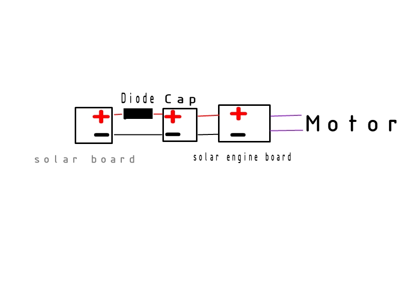
This is a small Project of solar energy we use 7pcs of bpw34 silicon photocell,each of them can provide about 0.53V voltage and 1.8mA current,that is very small,right? so we use a Circuit called “solar engine”,to Storage electric energy,and a Voltage trigger(HT7027A) to detect the Capacitive voltage ,when it reach 2.7V,the trigger will out put a “High level”,so it Trigger the entire circuit, start discharging,the Motor start working.Repeat this process The small gear motor will drive gear, the robot will move on and off……
(this is the Circuit diagram)
Ok,now Let’s start building this project
VEDIO
First we need soldering the Circuit then we make Mechanical parts
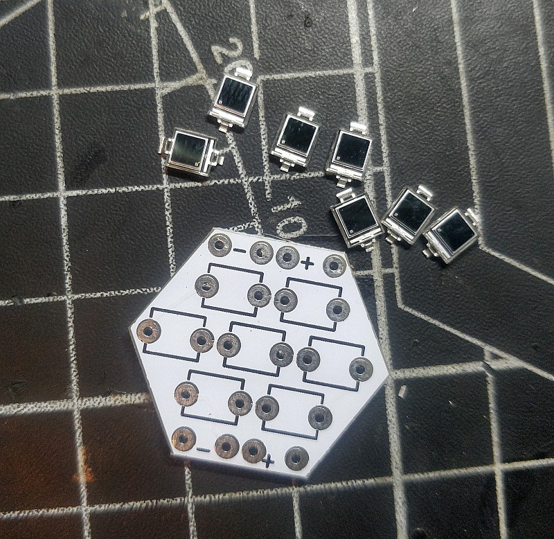
Step 1: Solar Panels
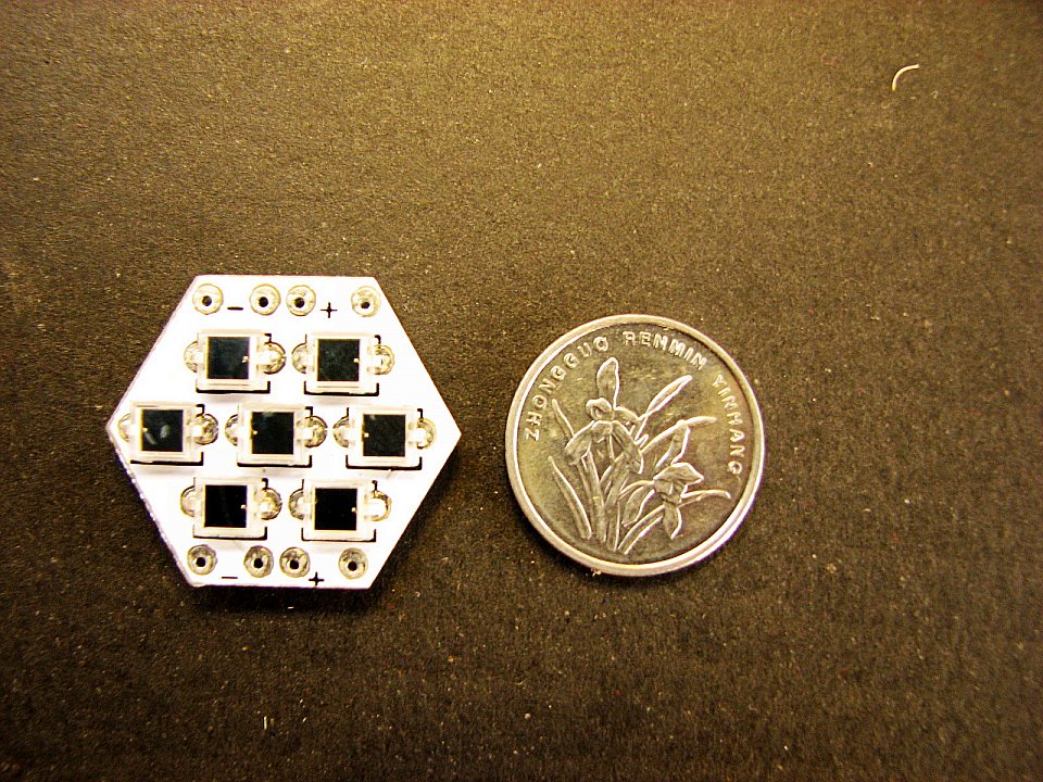
the BPW34,each can provide 0.5V and 1.7ma it have positive electrode.when you soldering it on the PCB,plz do not get it wrong
Please look at the picture below carefully and weld according to the picture, especially pay attention to the position of the small dot inside the red circle!!!!!!!!!!!

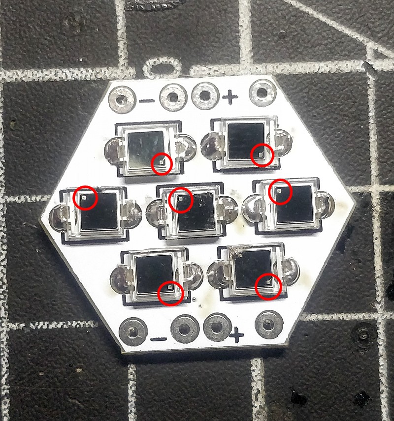
7pcs of bpw34 is series connection
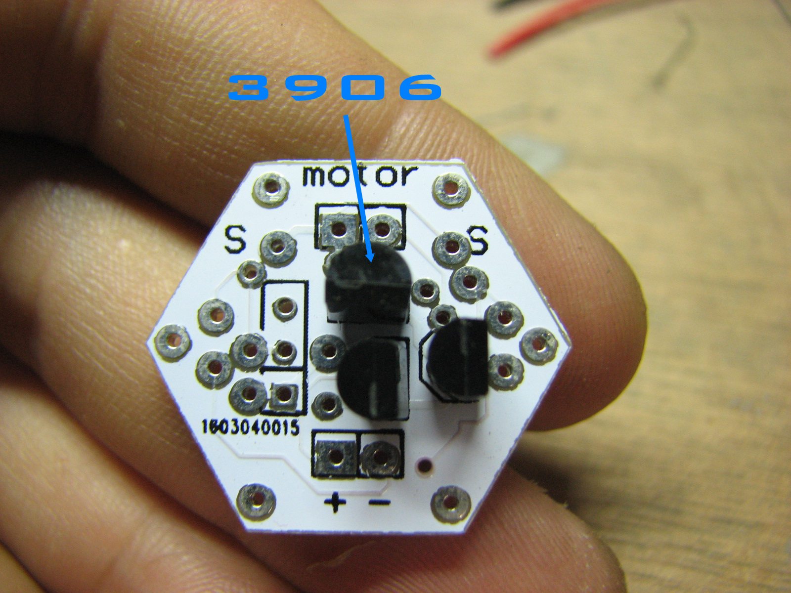
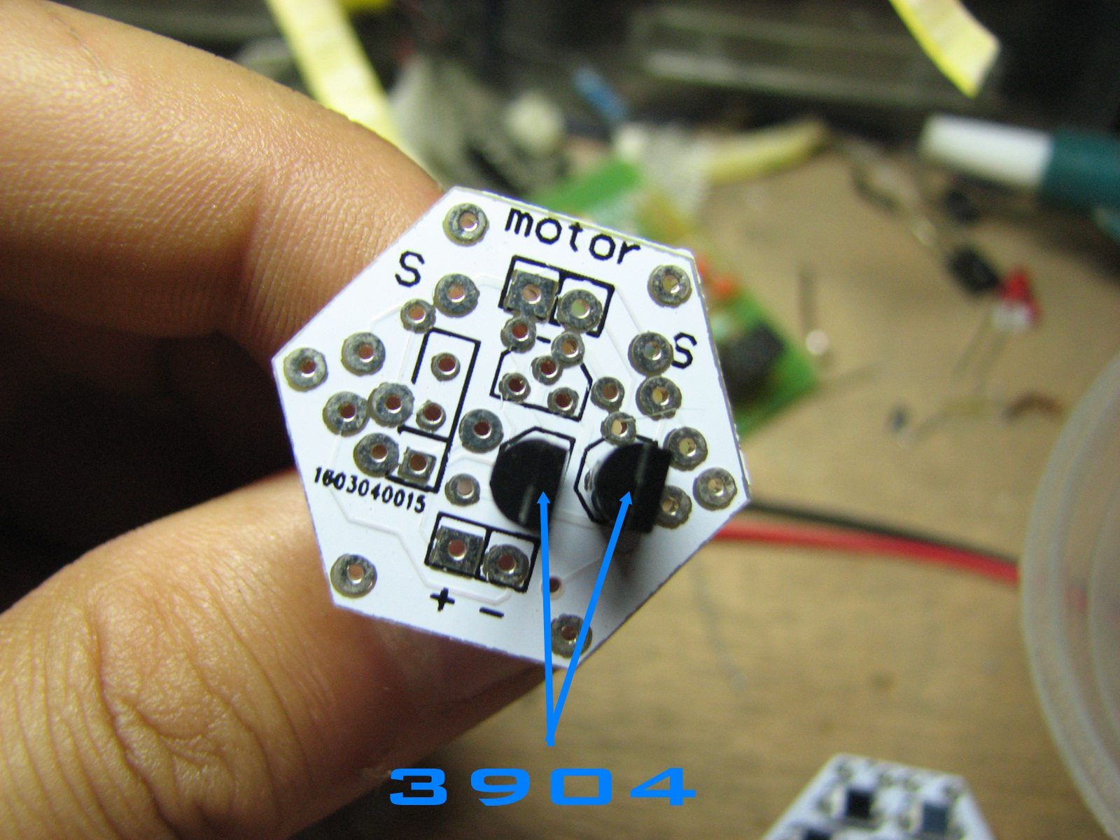
Step 3: The 2n3904 and 2n 3906
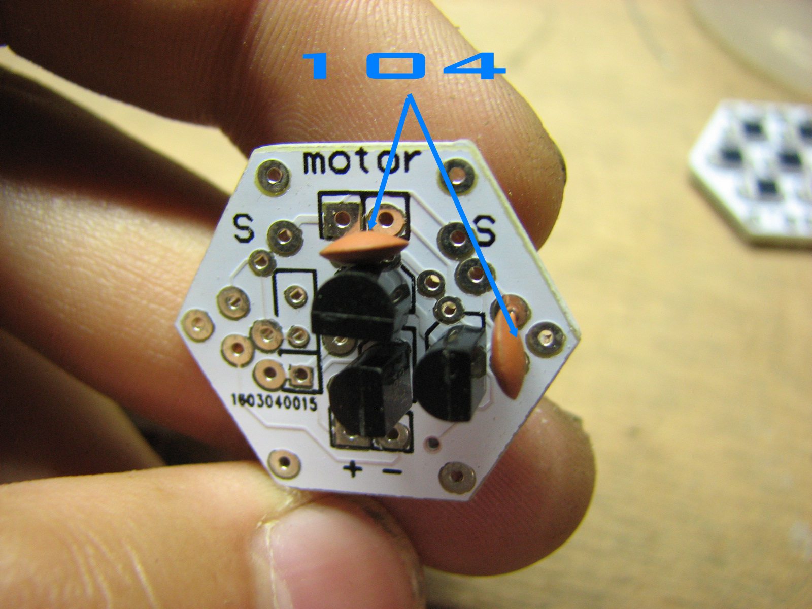
Step 4: Soldering the Cap 104 and CBB Cap

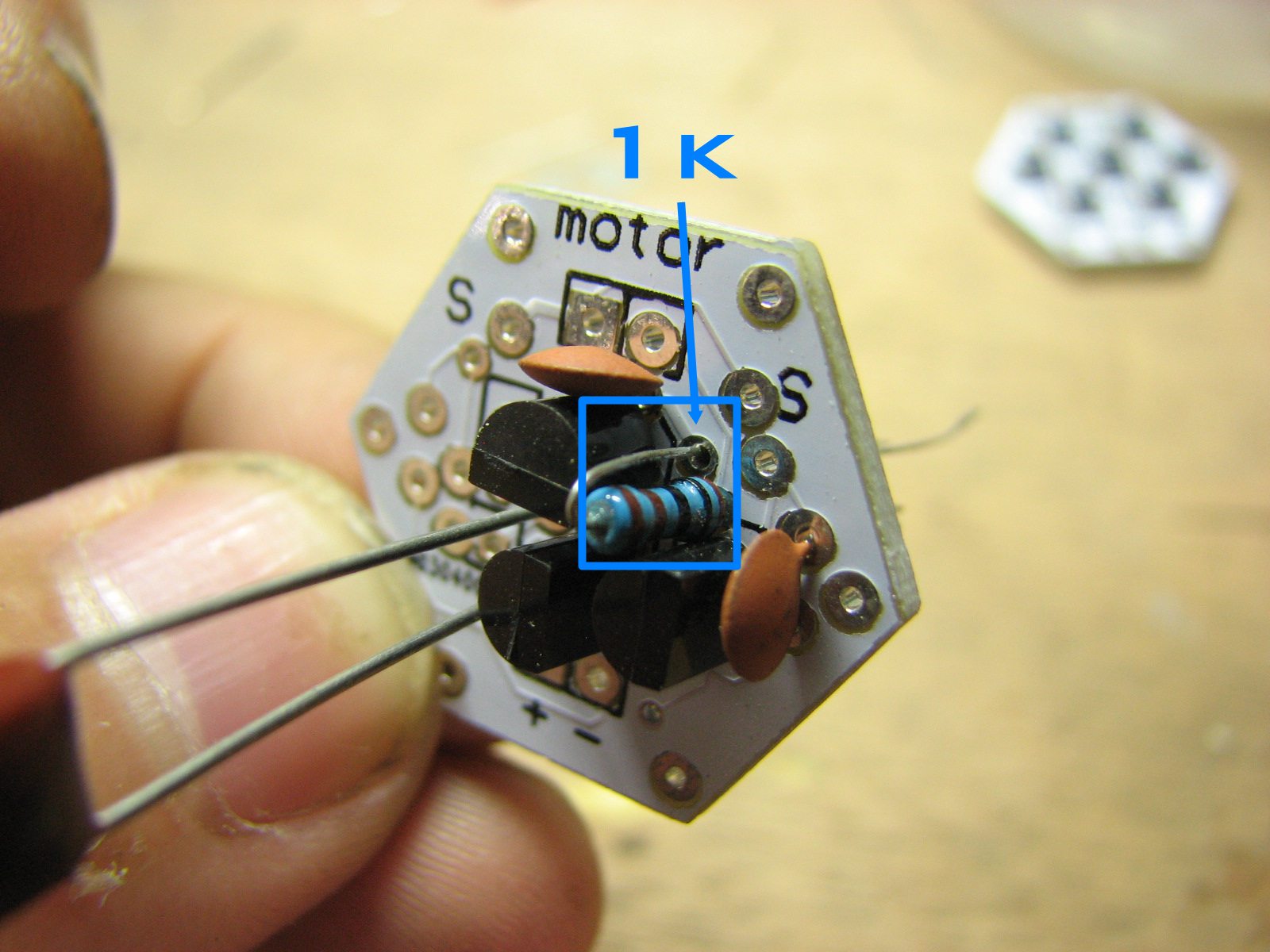
Step 5: Soldering the 1K Resistance
Step 6: The Ht7027 Socket
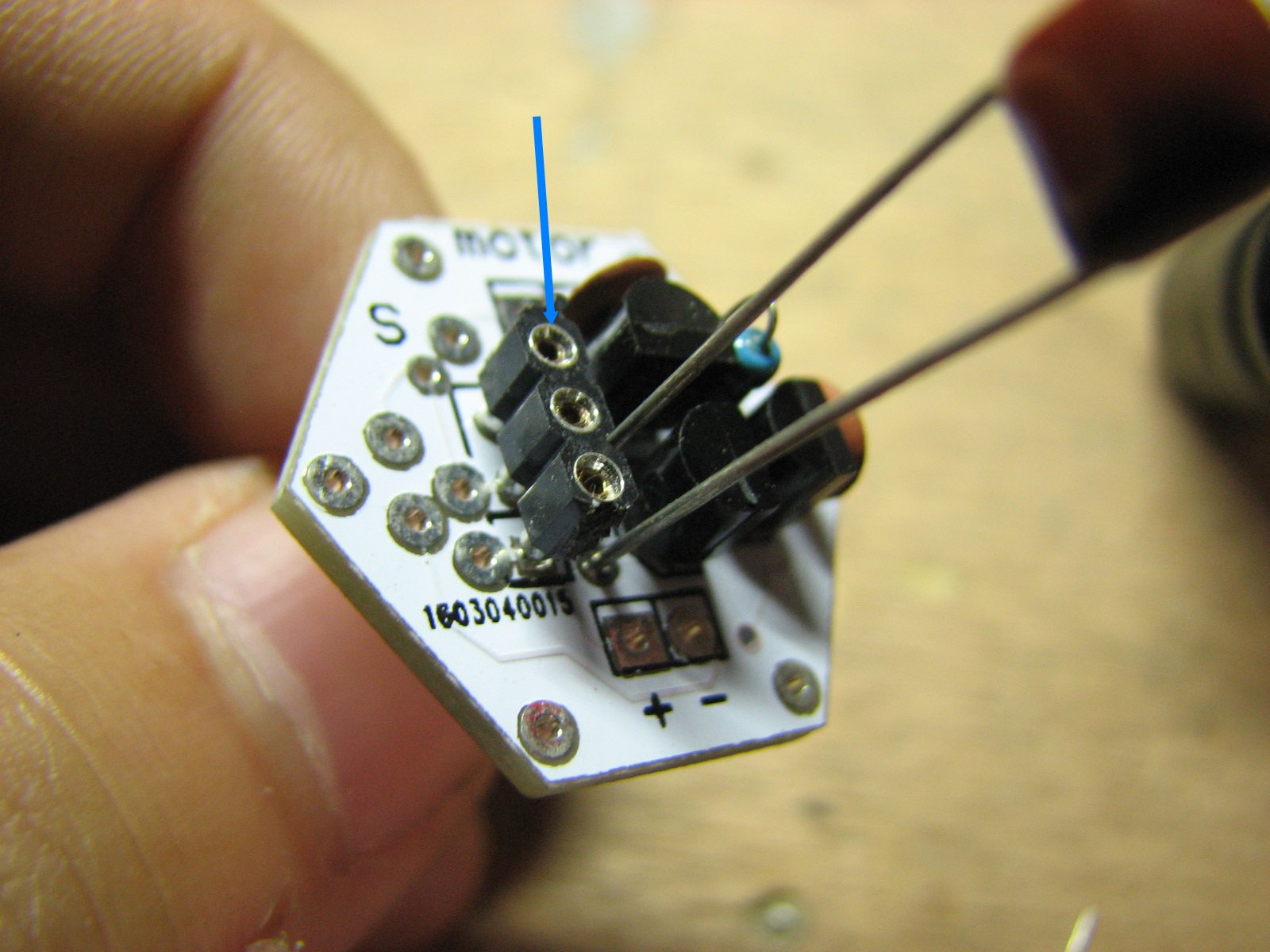 this is for installing the ht7027 trigger
Step 7: 100k
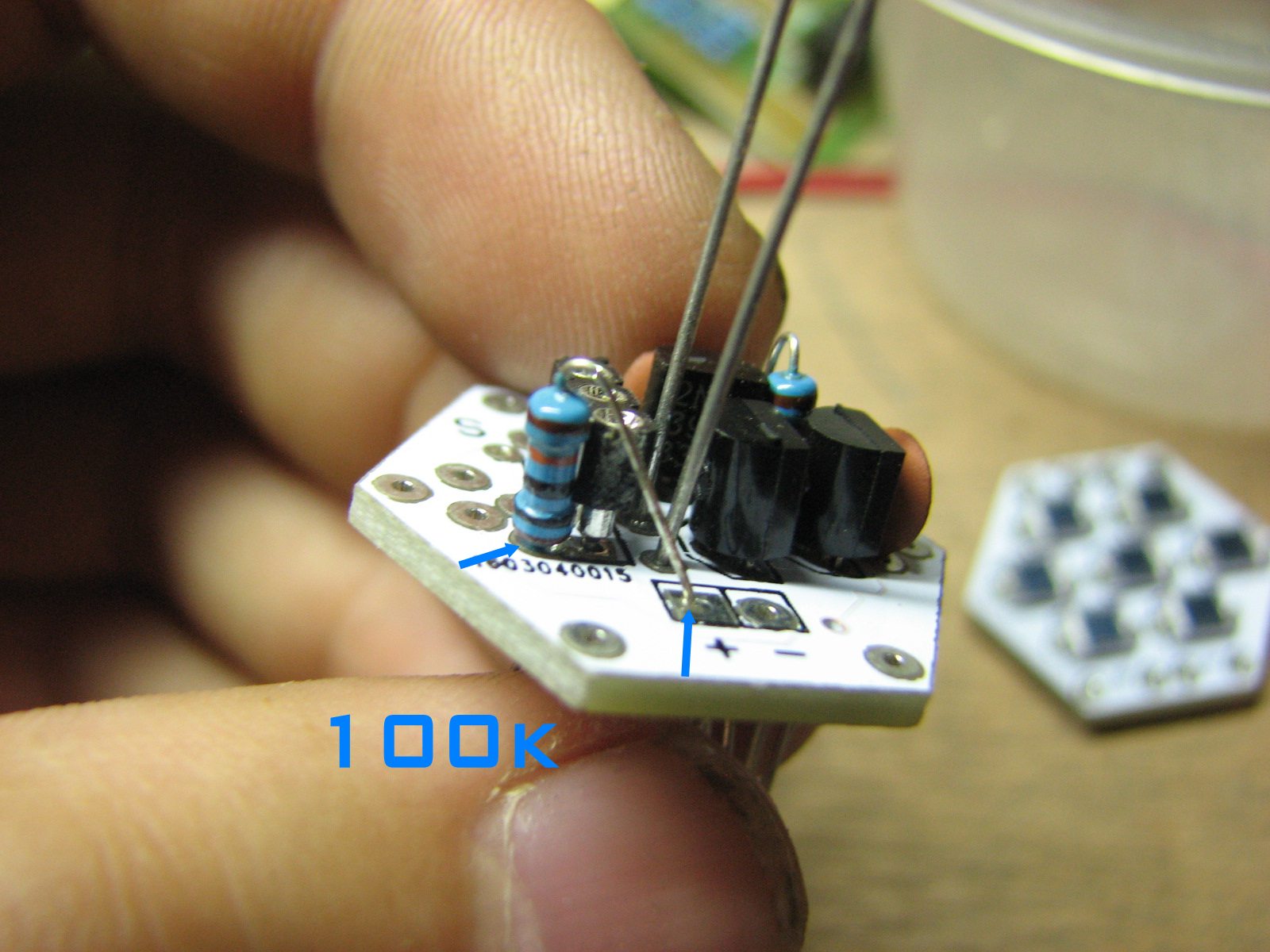 the 100k resistance is Pull up resistor for ht7027 out put
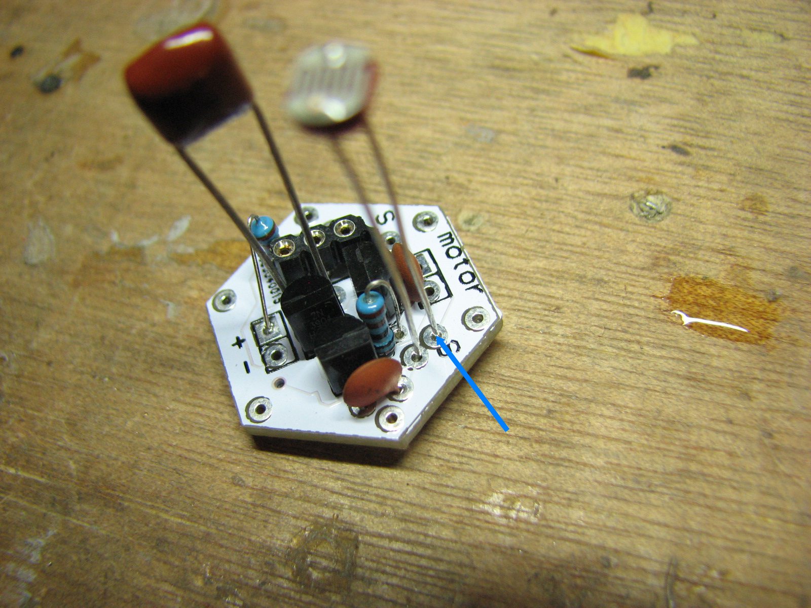
Step 8: The Trigger

Now we already finish the PCB,next we star building the Mechanical parts, need a break?
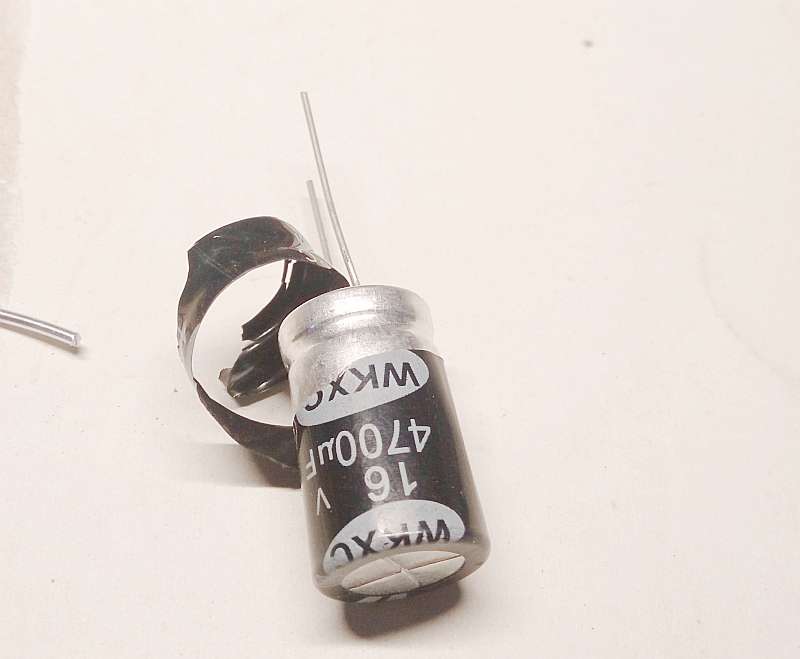
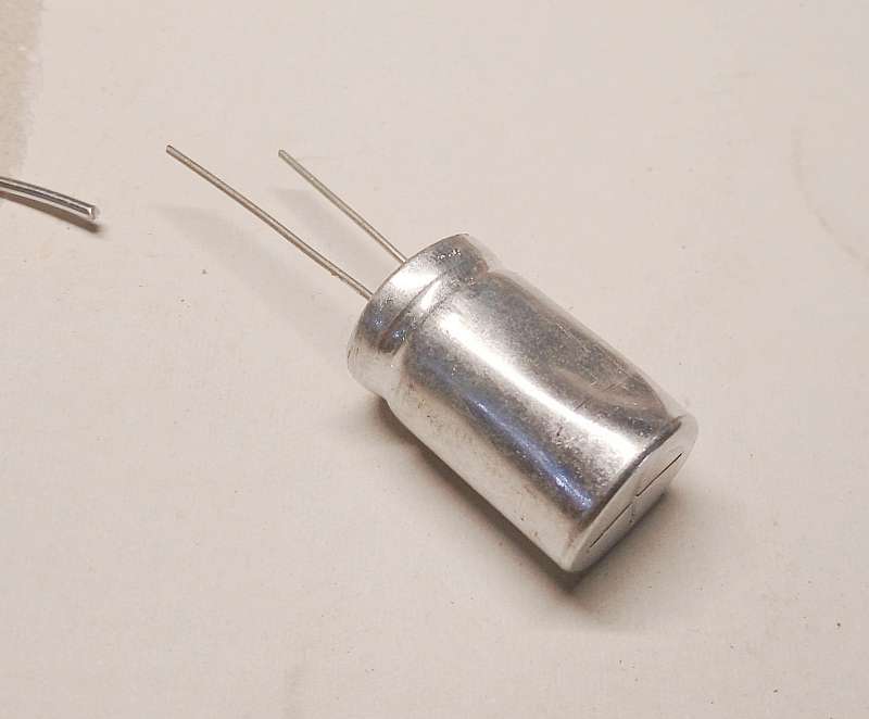
Remove the protective cover of the capacitor with a knife
connect the Solar panels to solar engine,find the Rectifier diode,Notice the positive and negative poles, the black line position,and do you still remember the “+” foot pin of the Capacitance?it is inside need the motor,do not mistake this,so the diode one side connect to the solar panels “+”,and another side connect to the “+” foot of capacitance,but the “-” foot is soldering a metal hard wire,that is for support the solar panels,I’ll connect the capacitor “-” and solar panels “-” with a single wire later and you need a hard metal wire to Support the solar engine board,like picture(it is solder to the “+” foot of the cap) see?the wire connect the “- ” of solar panels to the CAP “-“,and Before you have a diode connected their cathode,so now our solar panels has a Energy storage,and the diode make sure that When the sun is down, the electric current doesn’t go back

The circuit is connected, and the rest of the design can be designed randomly.