

Spark Gap Tesla Coil DIY-Type11
Building a high-voltage project – Mini Jacob’s Ladder
2月 15, 2026This is a spark gap Tesla coil
First to complete this kit, you need to prepare a 12v 2A power supply yourself
Then there’s the soldering iron and glue
We provide 2 types of tutorials, one is video and the other is pictures
Important notes will be emphasized in the pictures. If the video is too fast for you to understand, you can watch the following pictures.(This is Type9,vedio is Type8.The only difference between them is the discharge gap, so we only make changes in the last step. The video is still type 8.)
DIY VEDIO(The vedio is type8,yours is type11,The soldering parts of the circuit board are the same, but the final assembly is different, You can use it as a reference)
The following is a Instruction picture that explains the key issues that need attention.
If you think the video is too fast and unclear, you can look at the following pictures.
One more thing, this kit does not include a power supply, you need to prepare it yourself
12v 2A is fine
Interface reference picture


10k resistor
This is only used as a current limiter for the power LED indicator and has no other use.

Led
When the 12v power supply is connected, the LED will light up

20kv high voltage diode
Pay attention to the blue line and weld it according to the picture position
it’s important

You also need to pay attention to the welding position
Thick lines are welded to it


The circuit board has reserved positions for 5 capacitors
Our kit provides three by default. You can purchase 2 additional capacitors to see the difference in discharge effects.
This capacitor model is 20kv 17mm
Both installation positions are ok

The black circuit board is the oscillator
Using microcontroller to drive 4 mos
Such a modular design can simplify the DIY of circuit boards


Solder two terminals to the “Gap” pads on the circuit board.
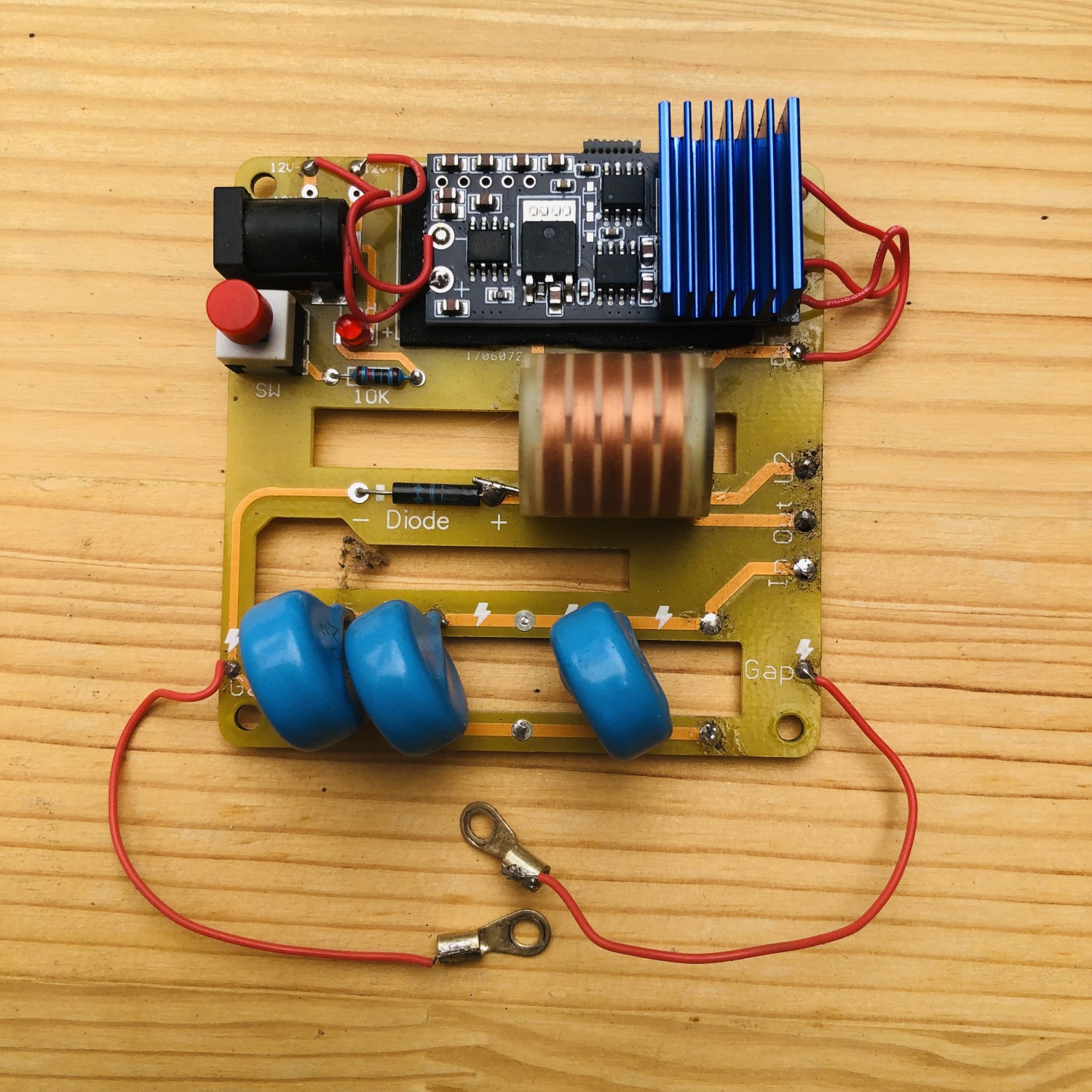
screw
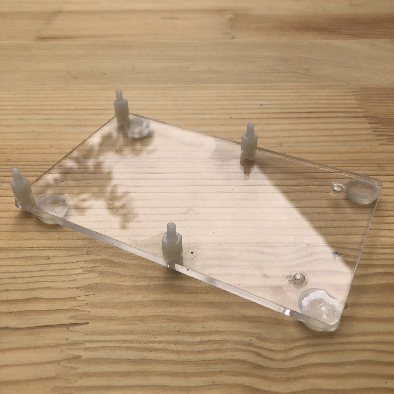
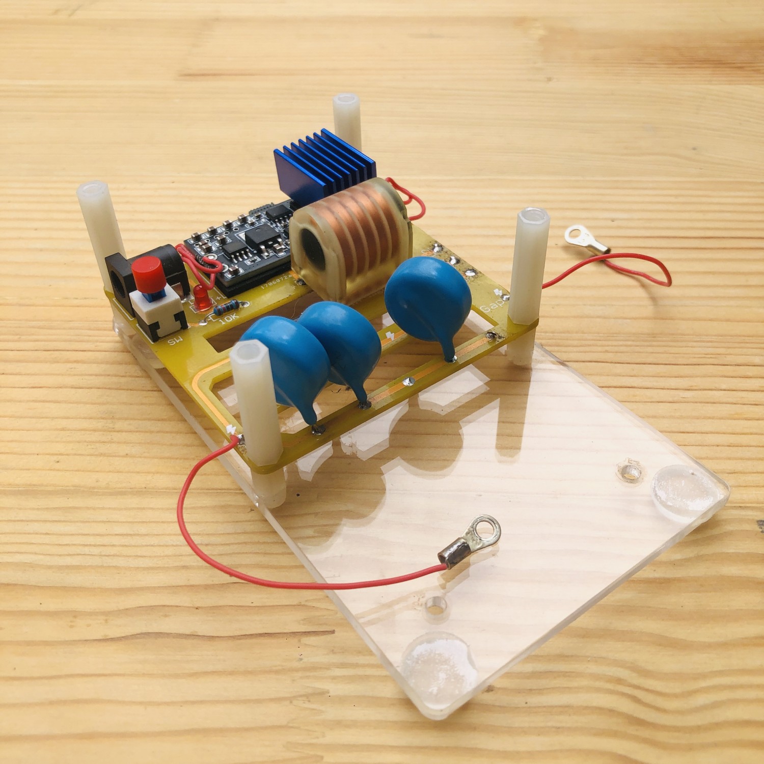
The primary coil is wound clockwise around the frame, using heat shrink tubing. The wires are shown in the diagram.
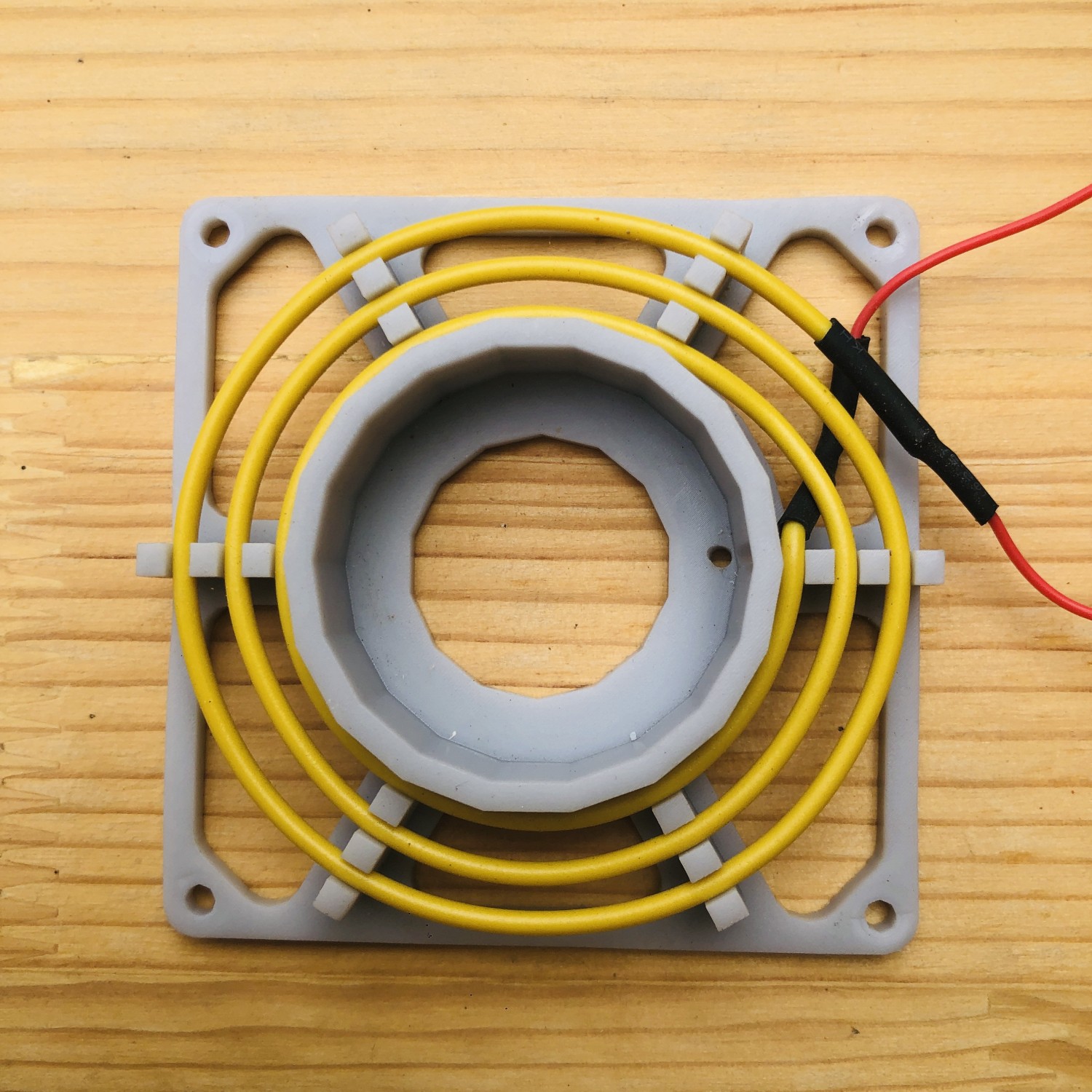
Screw
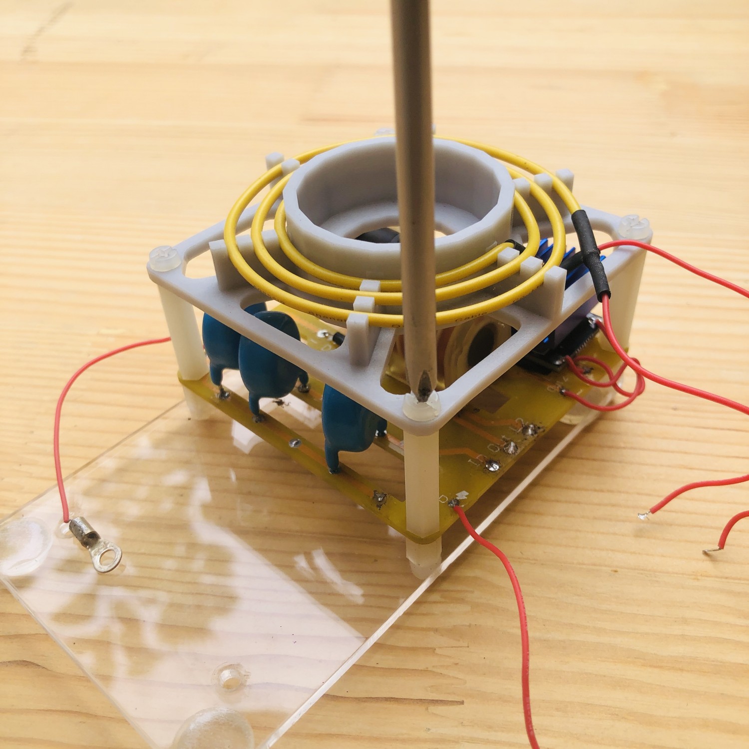
The wire inside is soldered to the “in” pad on the circuit board.
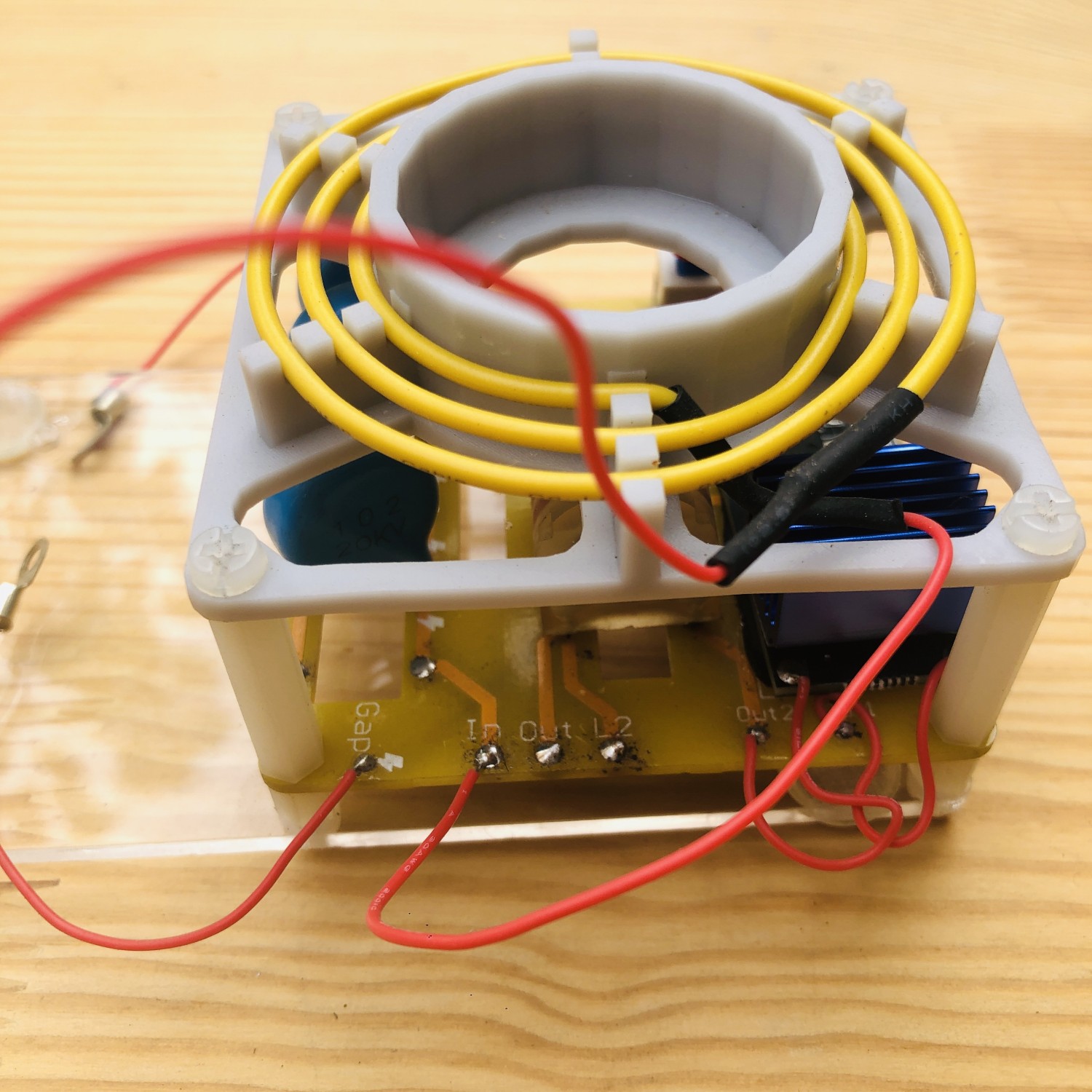
The outer wire is soldered to the “Out” pad on the circuit board.
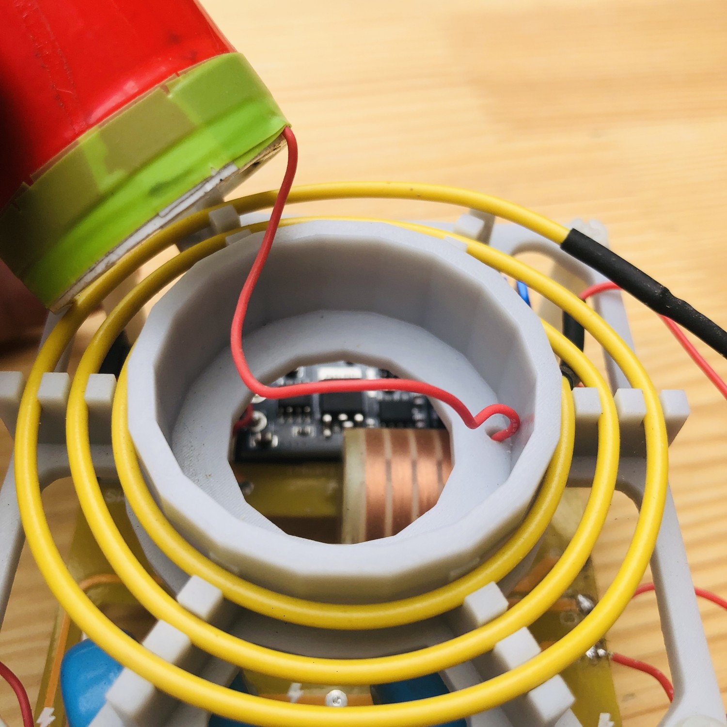
The secondary coil wires need to pass through this hole.
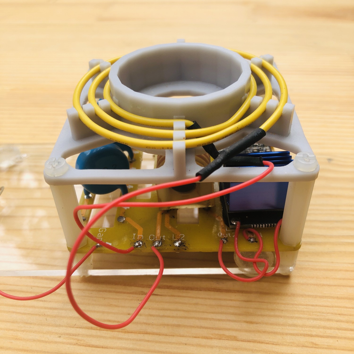
Then this wire needs to be soldered to “L2” pad.
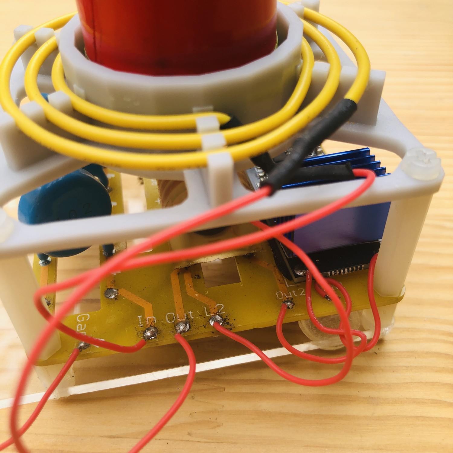
The black metal screw is used here.
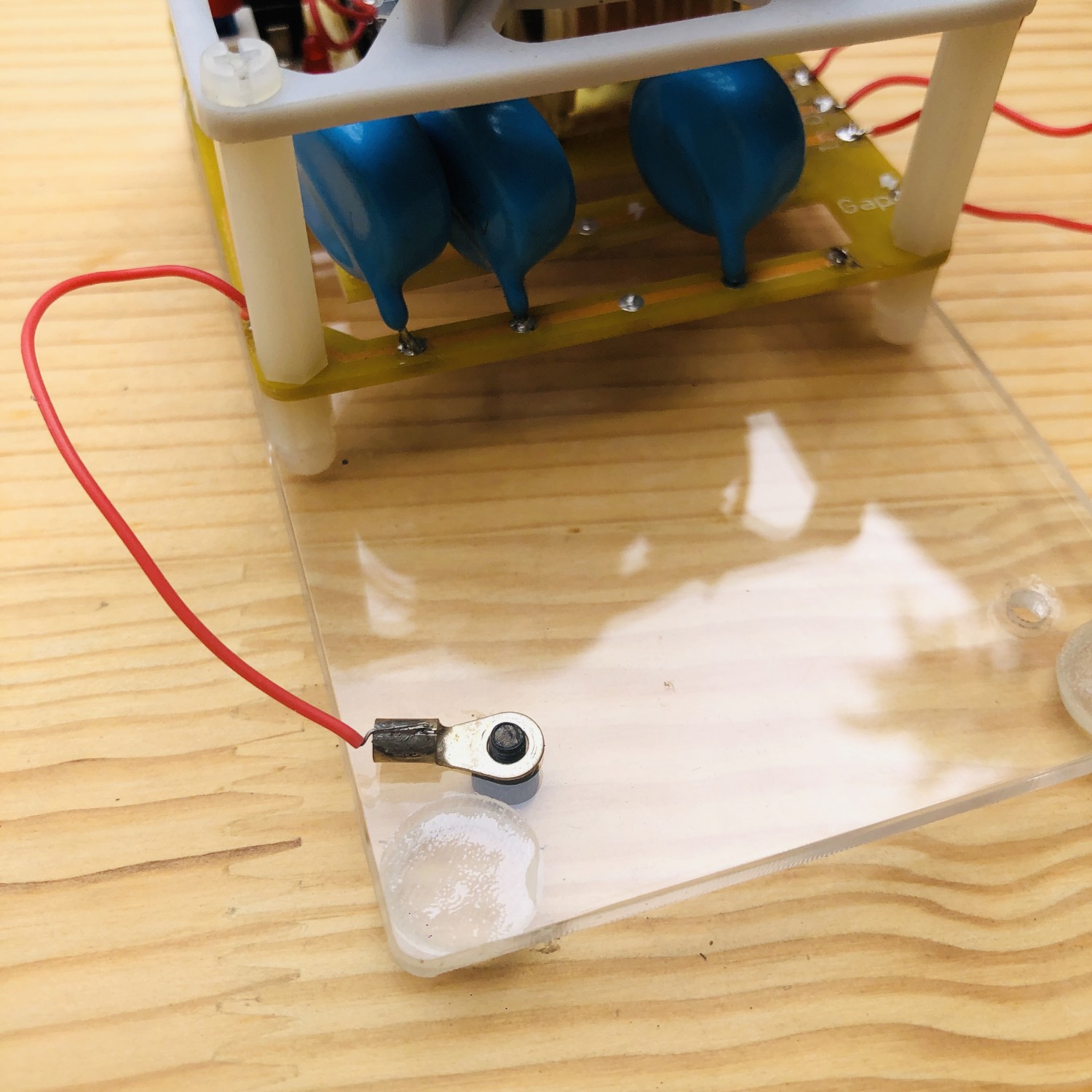
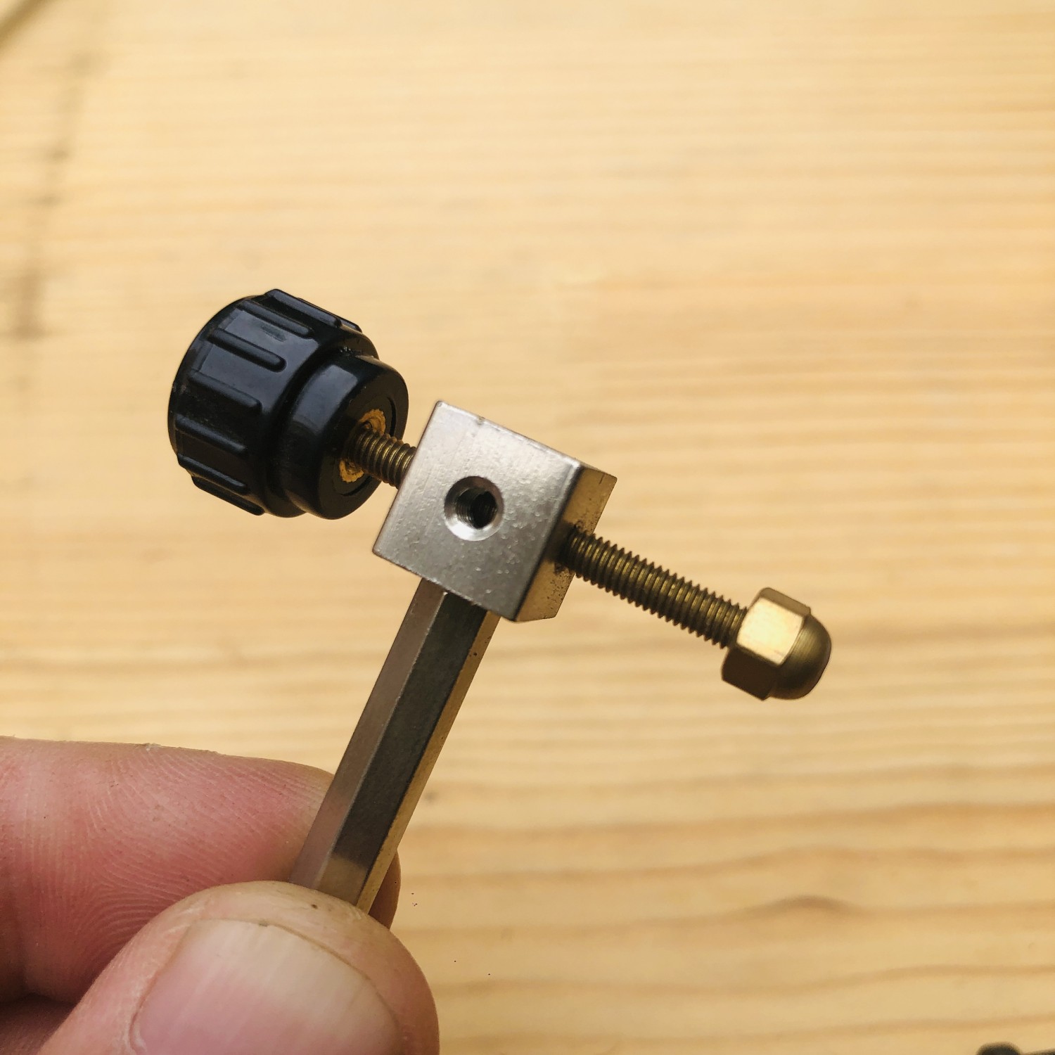
This is the assembly of the spark discharge gap.
Assembly complete.
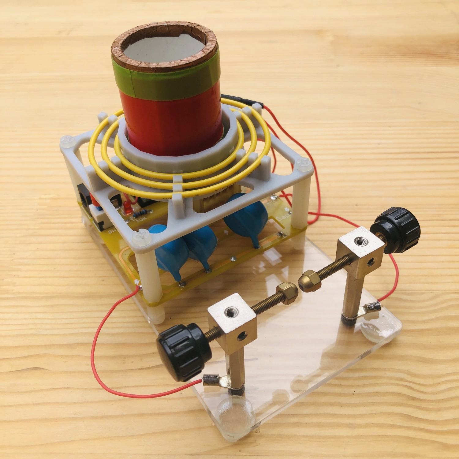
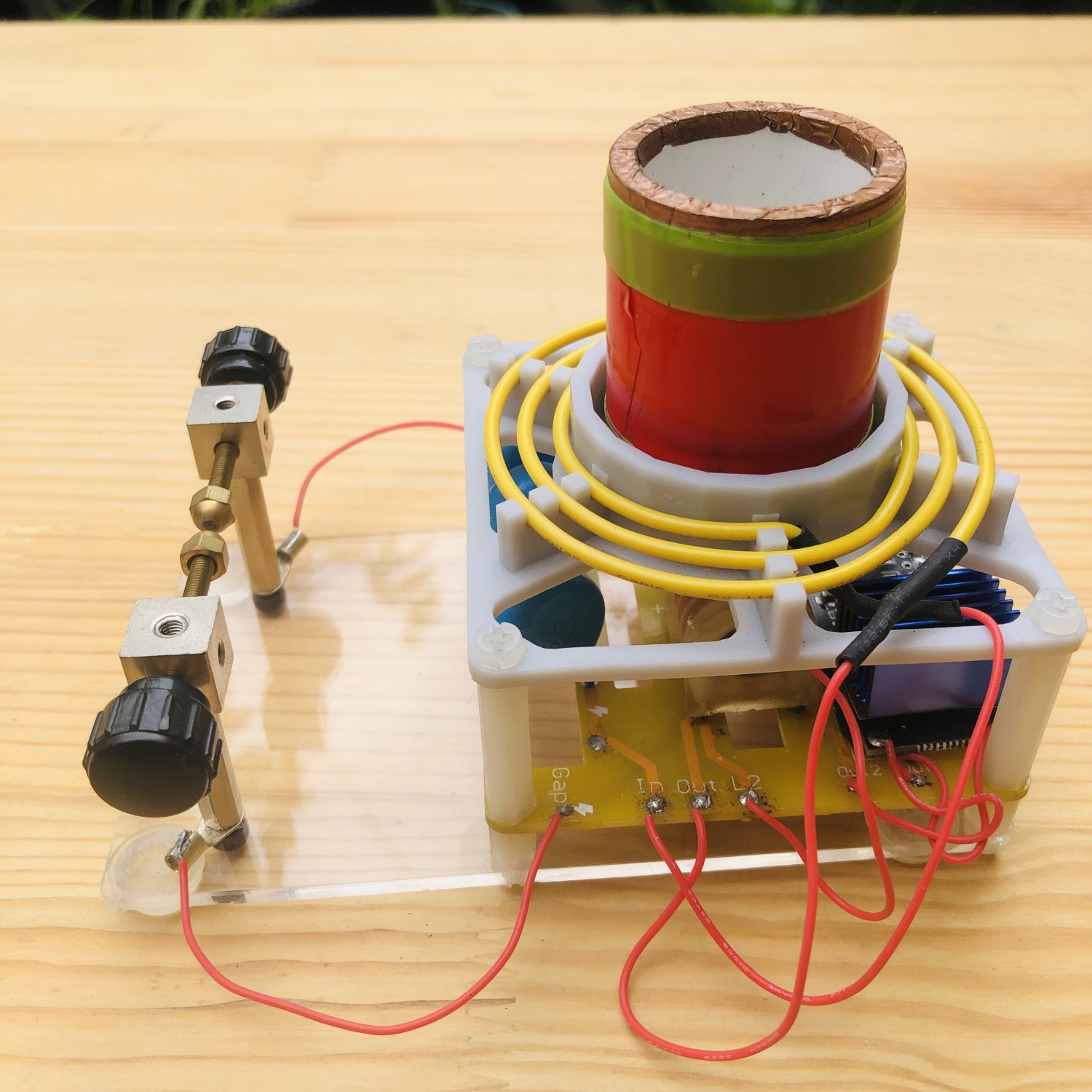
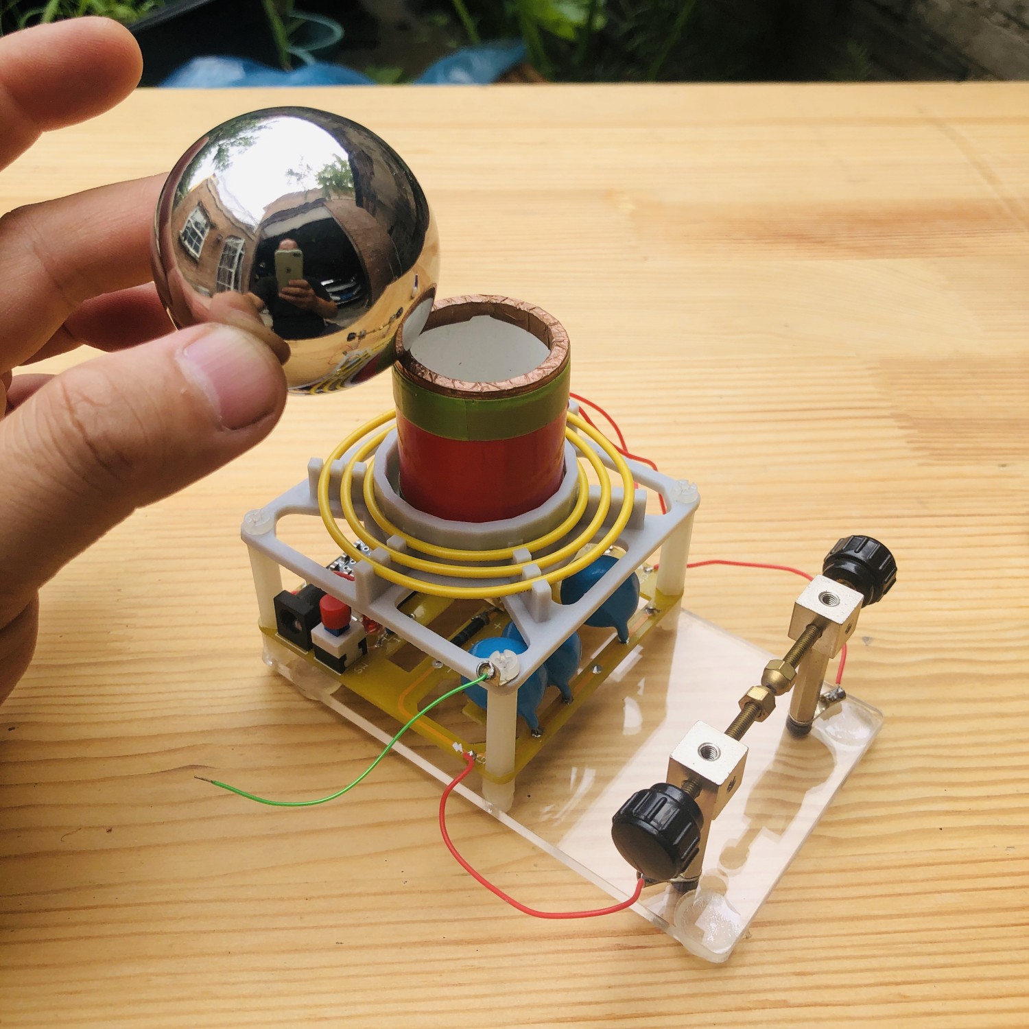
Use a 12V DC power supply. Do not operate continuously for more than 5 minutes. Cooling is required.
