
make a Mini table SGTC tesla coil Spark gap Tesla coil

Make a simple Bluetooth4.0 control robot
12月 2, 2017
How to make a mini mendocino motor?
4月 18, 2018
Make a Mini SGTC(Spark gap Tesla coil)
this Project is about how to make a 12v DC SGTC.Before maybe you have see a lot of SGTC like these
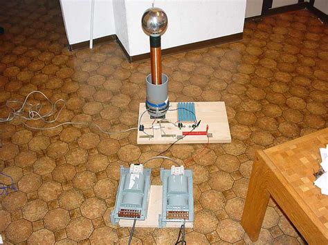
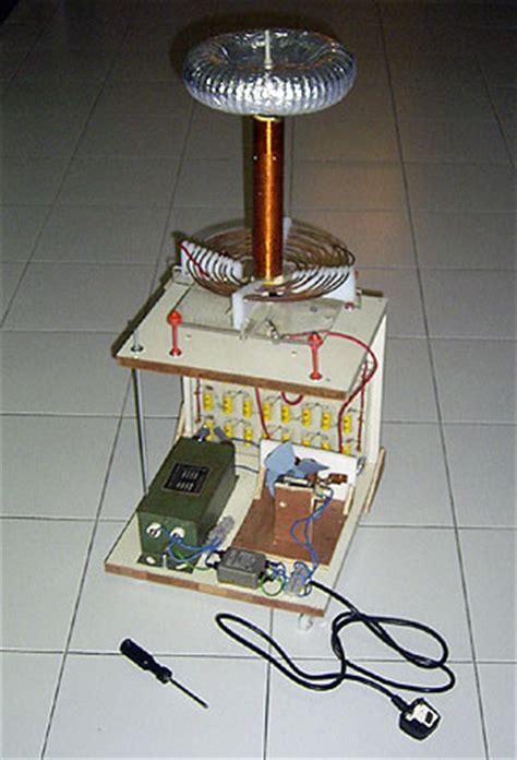
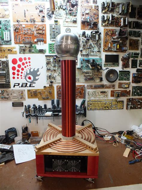
They are so big and use 110v-220v AC power,too danger and can not to be close to.so we want to make a small Spark gap Tesla Coil(SGTC),it is better use DC power like 3-24V,all its functions should be the same as big SGTC,just the power will be smaller,so we can touch the spark and don’t have to worry about an electric shock.We are glad we’ve finished this idea in this project.
Usually a SGTC contain High voltage signal generator,Igniter,Resonant capacitance and coil.The big SGTC is so danger and big because it use an AC power and many big Resonant capacitances,
If we can get a high voltage signal from a low DC voltage, we can get close to our target.It seems that Inverter high voltage generator can help us
Here it is
(This is a Special high voltage module for igniter,
Input voltage 7~15V
Output voltage 15KV~20KV
then we need a small Resonant capacitance ,According to the parameters of our primary and secondary coils(calculation formula is on google) ,8000v 0.01uf is ok
At last,interesting thing,the Lighter,we use Ceramic discharge tube,it has a small noise and we can choose 3kv-8kv breakdown voltage ,It is easier to damage,Belong to a consumable material, so it be designed to be replaceable And because of this you can choose to change the different breakdown voltage according to your own preferences, and there will be a different effect.
OK.We have finished the key parts instruction .Now let’s start making it
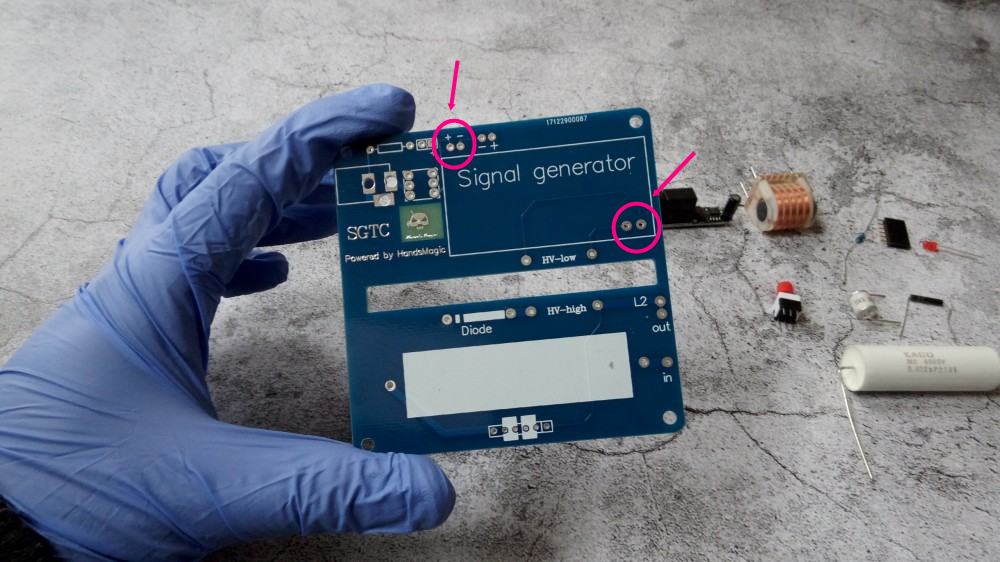
Step1
Scattered parts
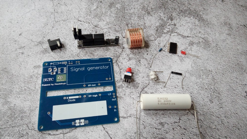
Foam is buffered at the bottom

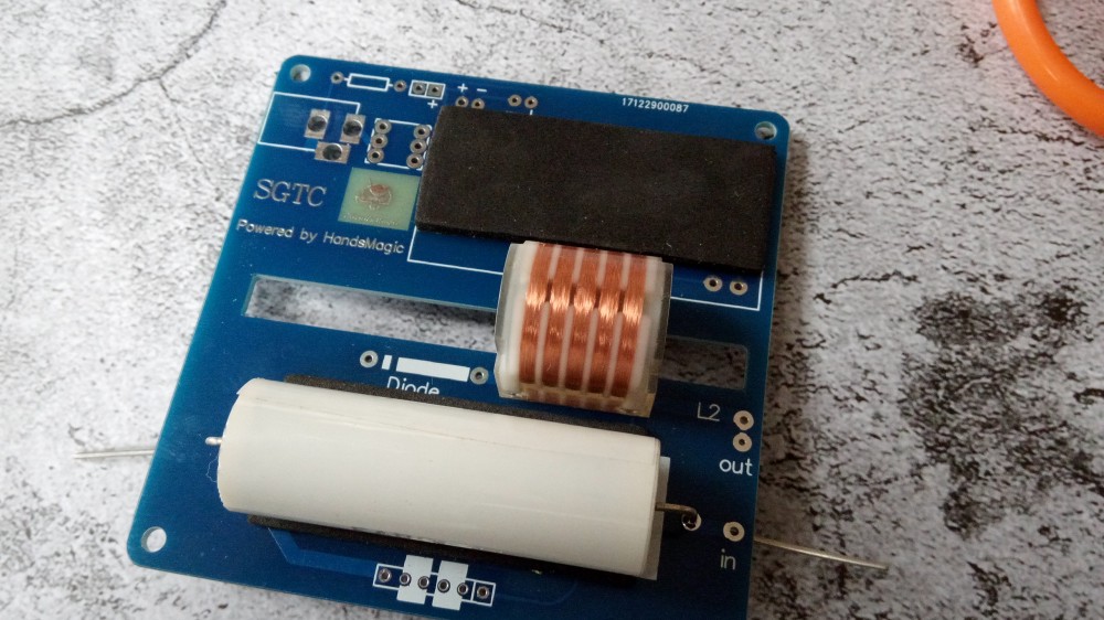
step2
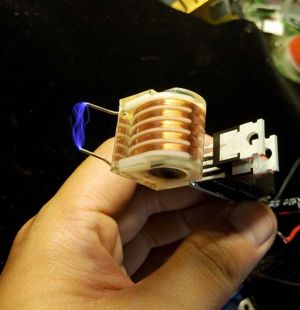
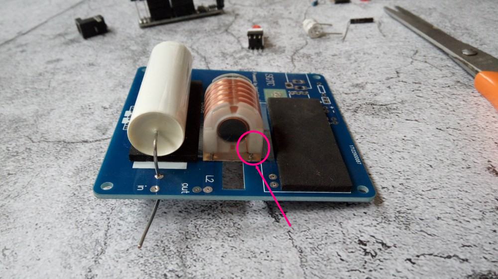
The transformer coil needs to be installed according to the picture, and the rough copper wire is the primary position.
Please look at the annotation on the picture
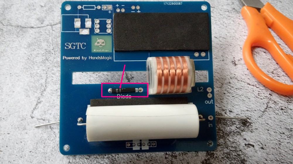
step3
High voltage diode
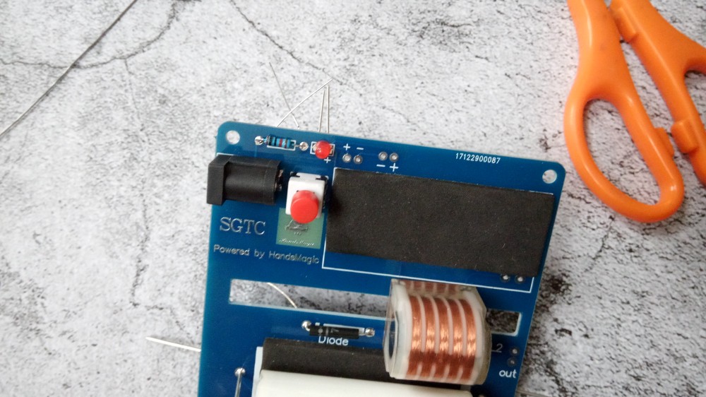
step4
Power indicator lamp,led long foot is +

step5
Power socket and switch
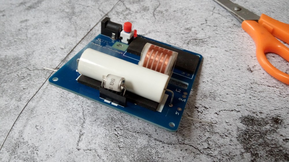
step6
Igniter socket

step7
the Igniter
step8
High voltage signal generator
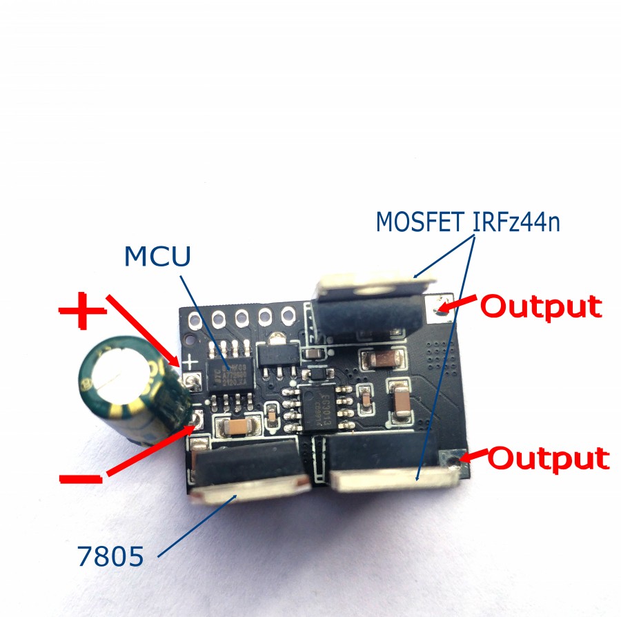

soldering to the right place marked in picture below


ok,the board finished
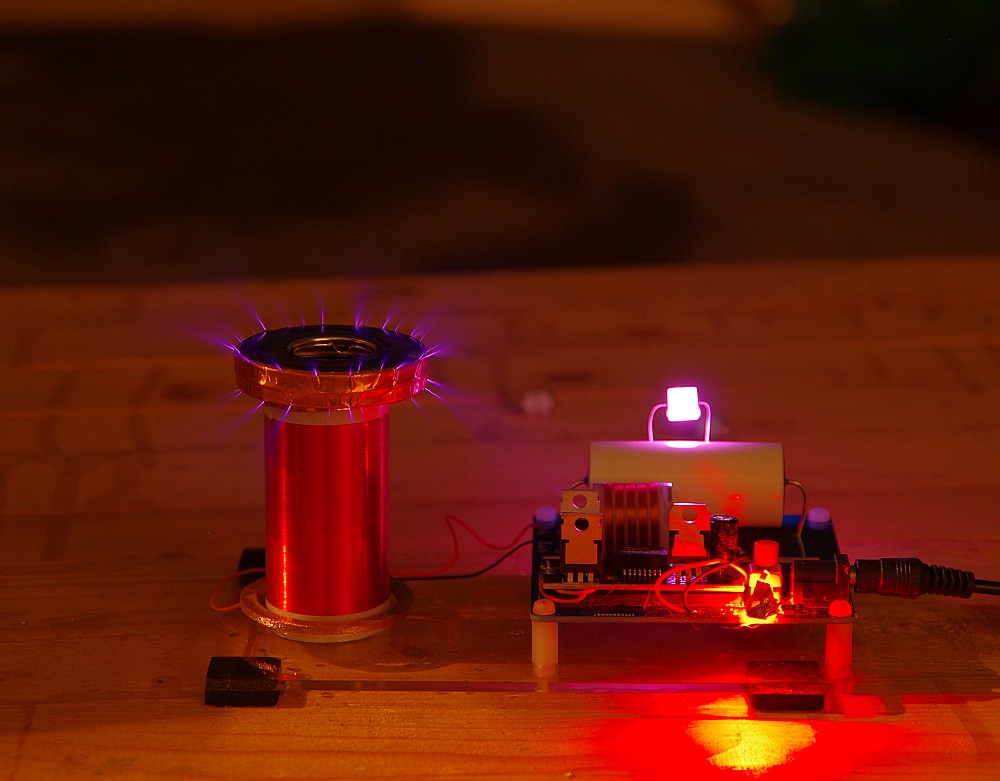
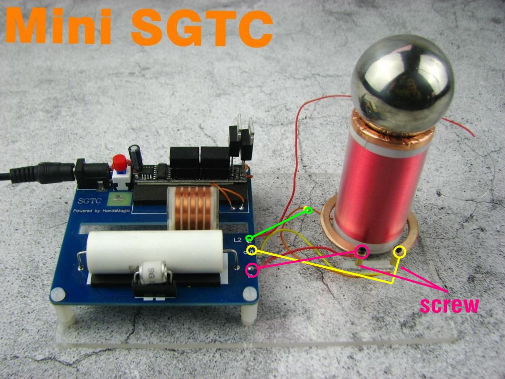
step9
now need connect the Primary coil and secondary coil to this board
the The copper ring is the primary,its left is “in” and right is “out”
the orange wire of the secondary coil connect to the board “L2″(in fact,the “L2” aslo is connect with the “out”,so in picture you can see the orange connect to the right screw,it is ok,and plz ignore the red wire soldering to L2 in picture)

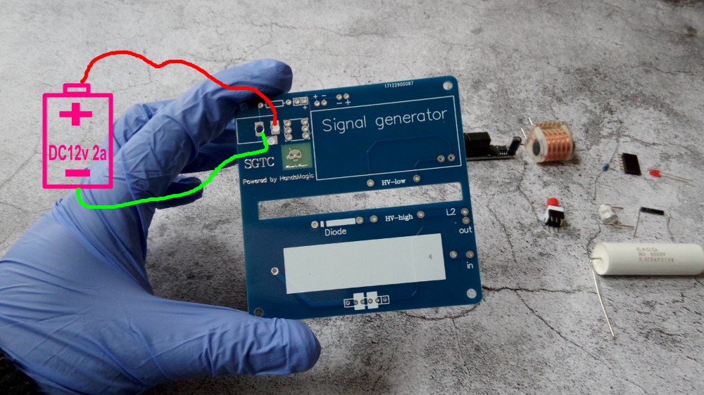
About the power suply:
you can use any DC12v power suply(make sure the out put current is 1A-2A)
For example:


if you don’t want to use the plug,you can solder two wire directly to the board,and connect them to your DC12v power
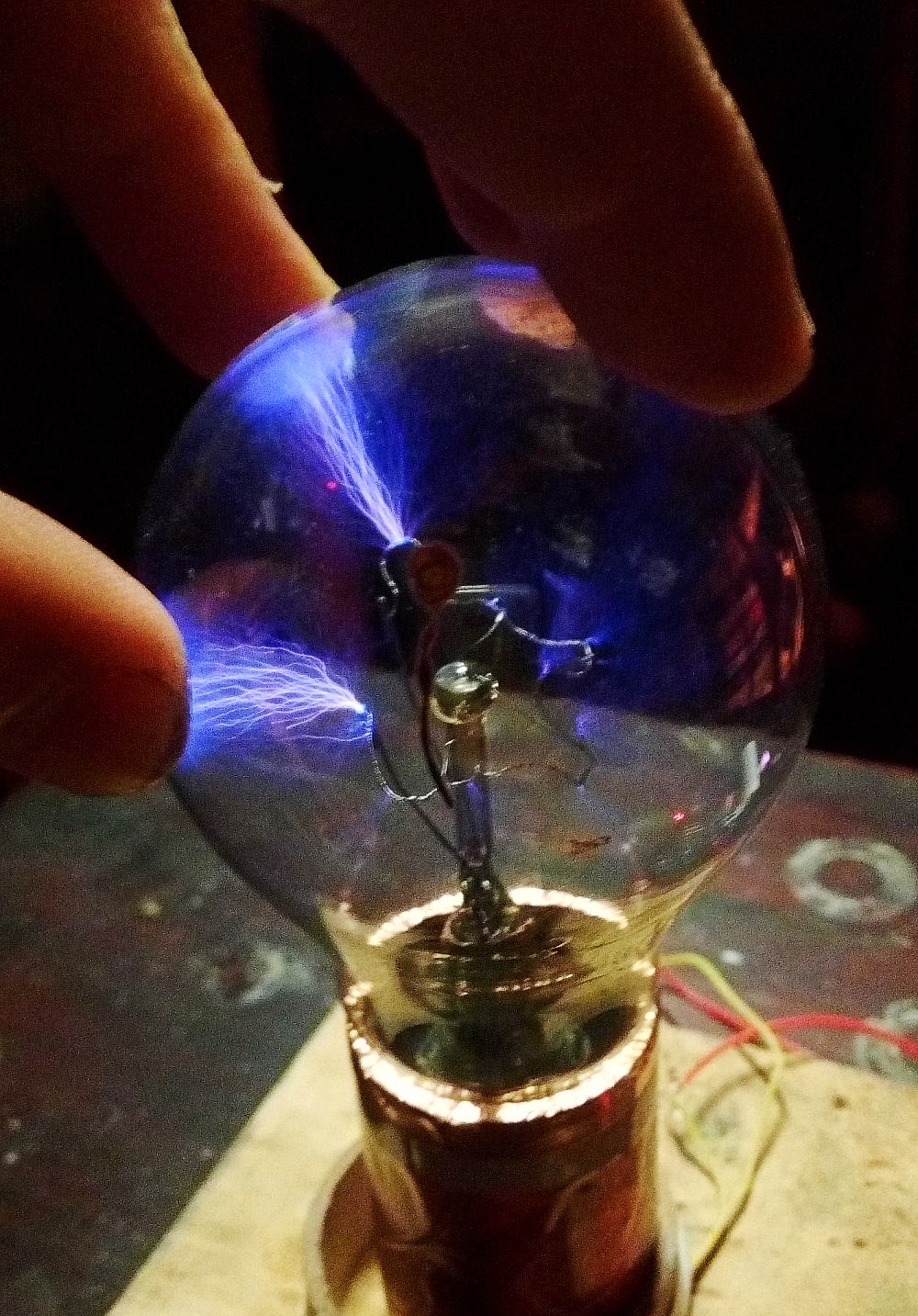
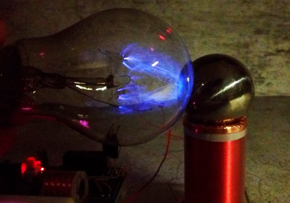
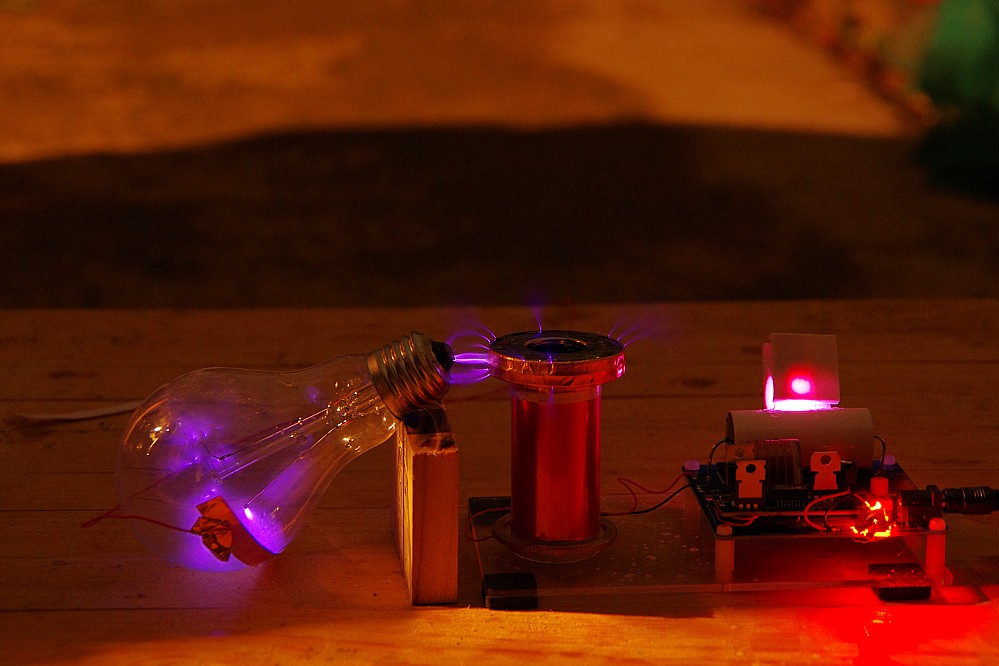
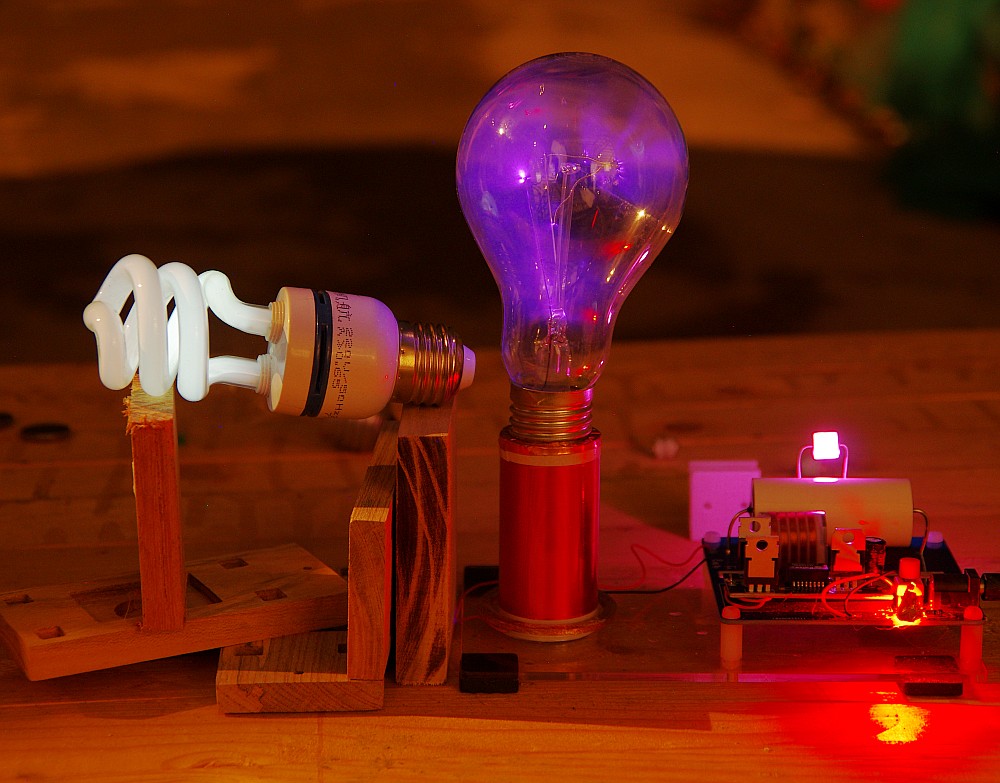
ok,all is done,12v dc power,you can use it now(plz use it in dark place,you can see the spark and arc)
find a Incandescent lamp