

Digital Clock based on esp8266-Clock4

NTP Clock LED Matrix Digital Clock
1月 18, 2023
Digital Clock NTP temperature humidity Display
12月 1, 2023This is a wifi clock .The clock use ds3231 as clock chip, precision is about 2ppm,that means it’s maximum error is about 1 minute per year.It can connect your home wifi through the esp8266 wifi chip .With some simple settings, you can control this clock over the network.It have a funny alarm, you can choose the alarm mode, whether it will keep ringing until you turn it off or only for a minute
Follow our step, you can make a cool network clock yourself
HOW to USE?Vedio
Now let’s start making this alarm clock
Welding Principles
Components are soldered from low to high
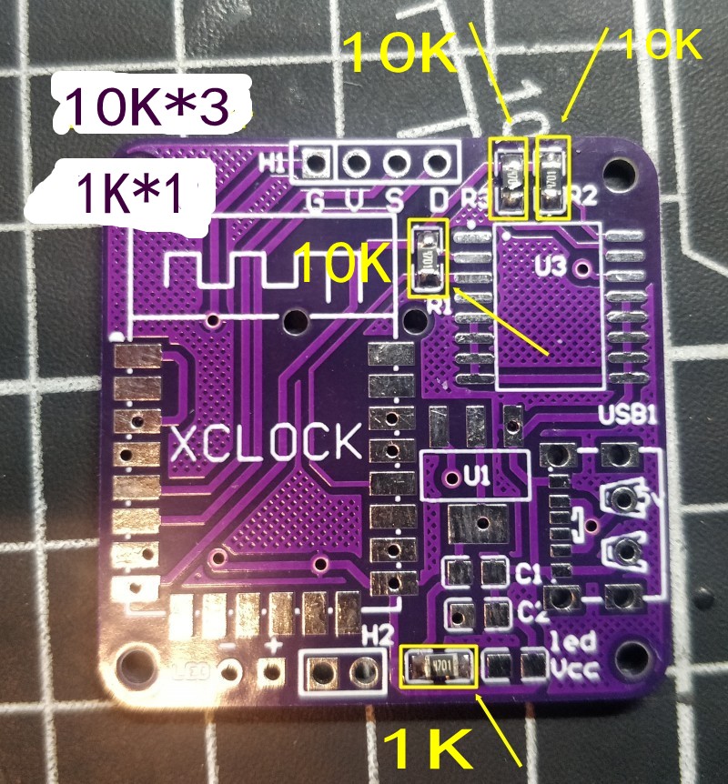
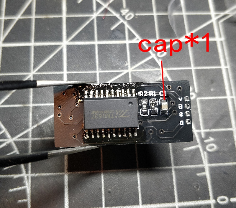
first solder the resistor and capacitor, this is 0805 SMD
Look at the picture, Solder the components to the corresponding positions on the picture
10K*3 and 1K*1
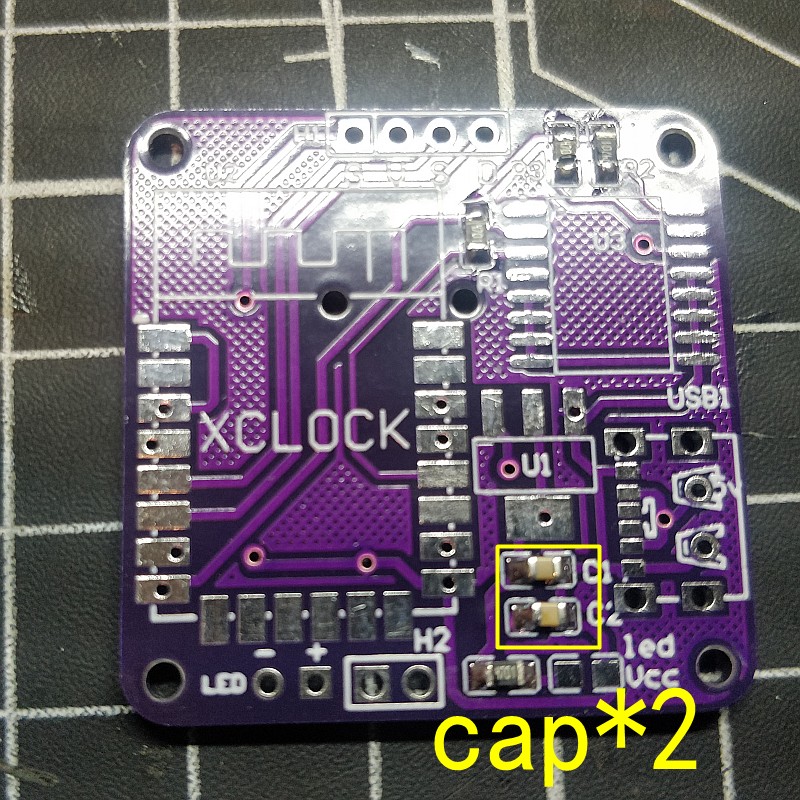
the back of the pcb
10K*1 and 1K*2

Next Solder the capacitor
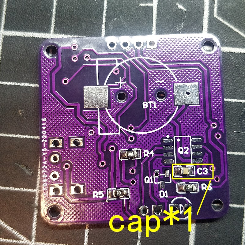
PCB back
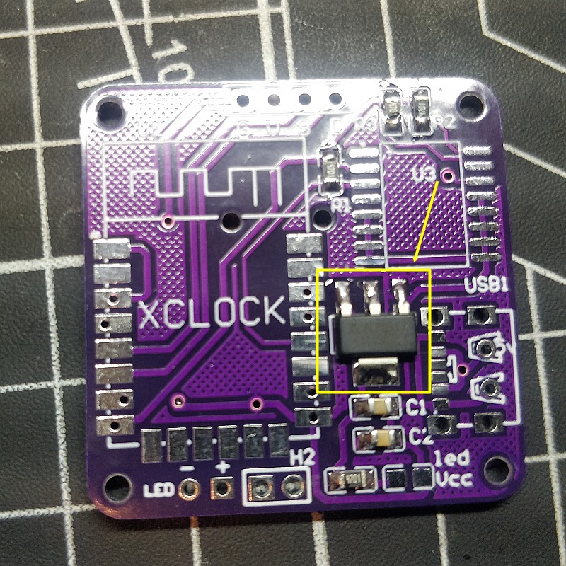
Welding power chip,LM1117
this chip can change 5v to 3.3v for the chip working
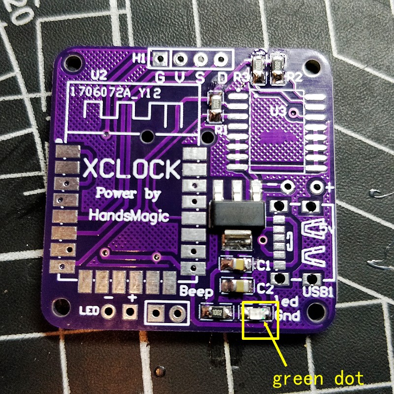
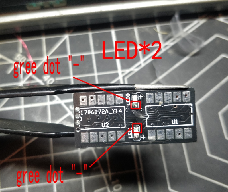
Welding power indicator led
LEDs have positive and negative poles
The green dot is the negative pole, the negative pad is soldered to the right side
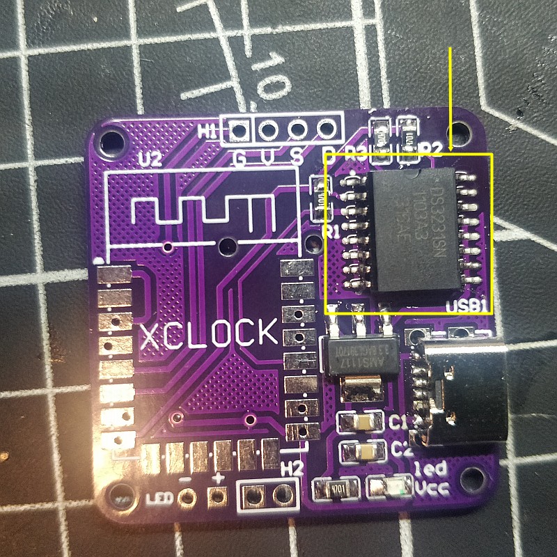
Clock chip,ds3231
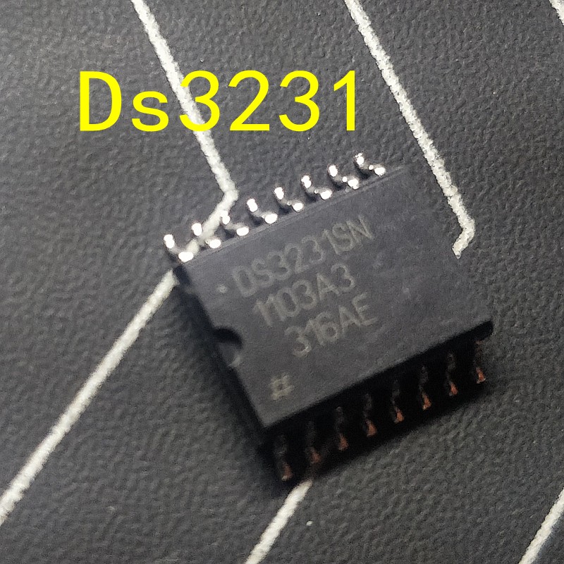
You need to learn to solder the smd , it’s not very difficult
This is the alarm clock chip, which stores audio files
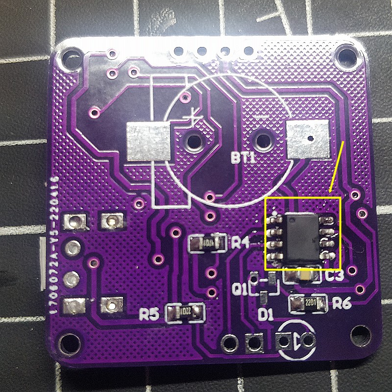
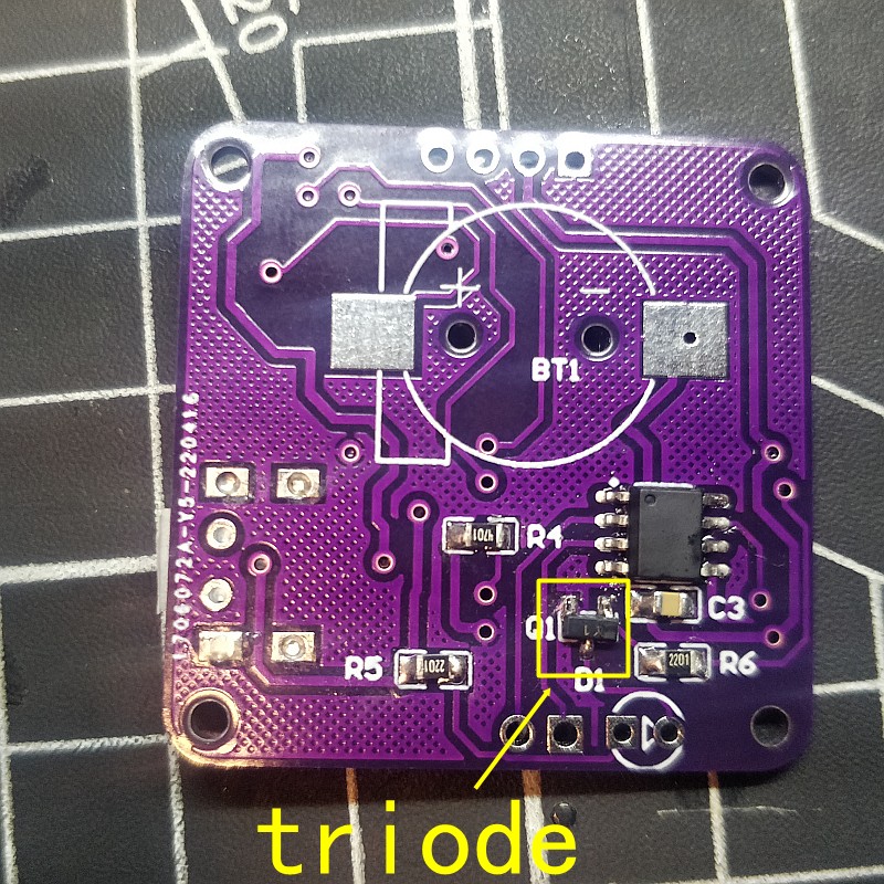
triode
This is used as led driver
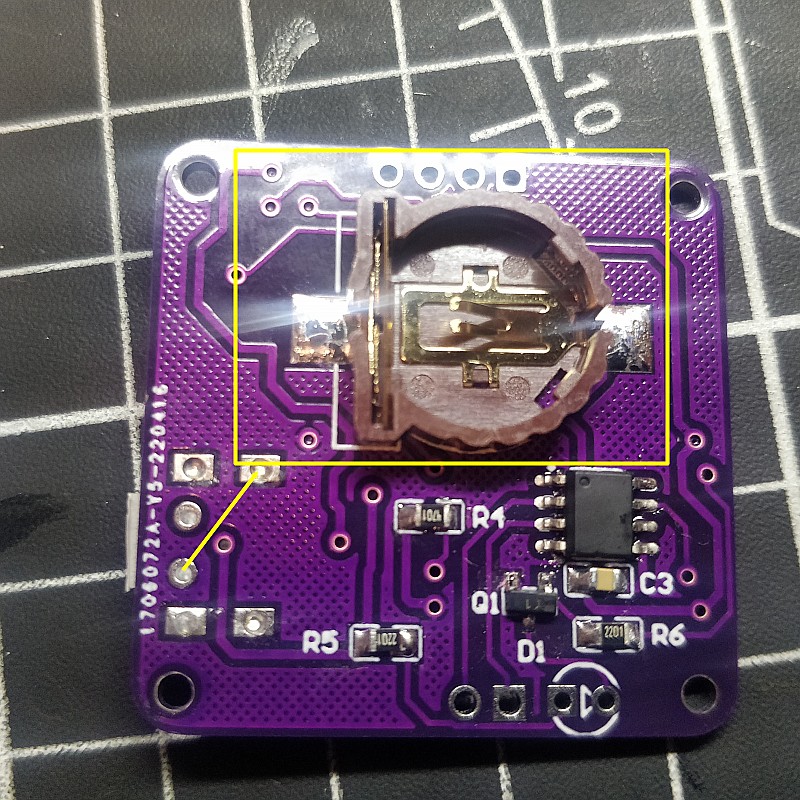
This is the clock chip battery holder
For power failure time memory(battery type is cr1220,you can by yourself)
This is the wifi chip which is used for network communication and for controlling the entire clock

Well, at this step, the main circuit board has been soldered
Next we will solder the digital display board
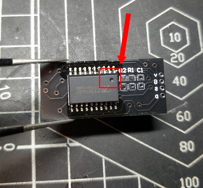
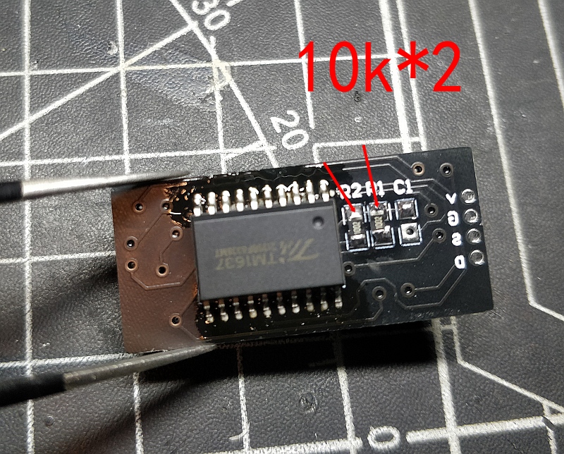
this display is based on TM1637 ,plz note that The mounting position of the chip
LED welding
It is necessary to distinguish the positive and negative poles of the led
as shown in the picture
Note the position of the green dot
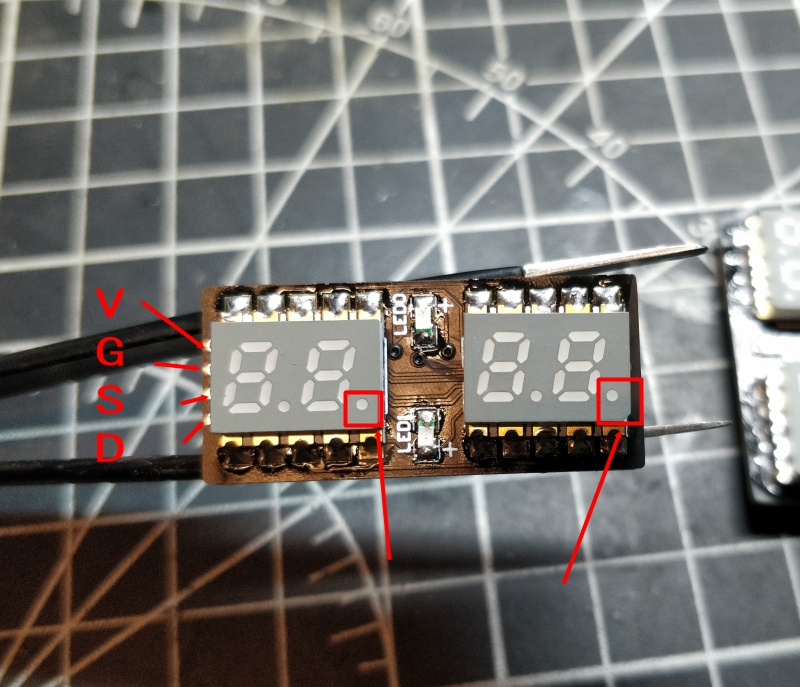
display digital tube
Pay attention to the installation direction of the digital tube
as shown in the picture
the “Dot” location
This is the base, wooden frame, screws, the installation is very simple


Then the extension cable for the usb interface
Note that the “+” on the board is connected to “V”
“-” connected to “G”


Next, connect the digital tube display module and the control module
The “VGSD” on the digital tube corresponds to the “VGSD” connected to the control board


Go through the bottom, so the wiring will look better

fixed with glue


For the speaker, use 2 thin copper rods and solder them to the pads corresponding to “beep” on the circuit board


Finally, the power test
For the setting method, you can watch the video at the beginning or the text below

Next is how to set and use this alarm Clock
First of all, you need a mobile phone charger, it can be powered by connecting to the type-c charging cable.
then configure wifi
phone – settings – wifi
Find the wifi hotspot “AutoconnectAP”, which is generated by the clock itself
To enter this AP, a password may be required, and the password is “password”
Then select the wifi of your home, enter the password of your home wifi, and click save
Wait a while, it may take 30 seconds, until the page disappears, then the oled screen of the clock will show the assigned ip address
Use this address, enter the address in the browser, you can set the clock(The vedio below is another type clock,but it is the same way to set the clock)