

diy clock type1

Diy table spark gap tesla coil -SGTC-type3
7月 2, 2018
diy clock type2
10月 17, 2018
Clock diy(type1)
Most of the patch components have been soldered, only need to solder some plug-ins, it is very simple,let’s start………..
A total of 2 boards, we first solder the components on the two boards, then connect them with wires.
please note the the led dot matrix direction,look at the picture,beacause if you are wrong,fix it is not easy
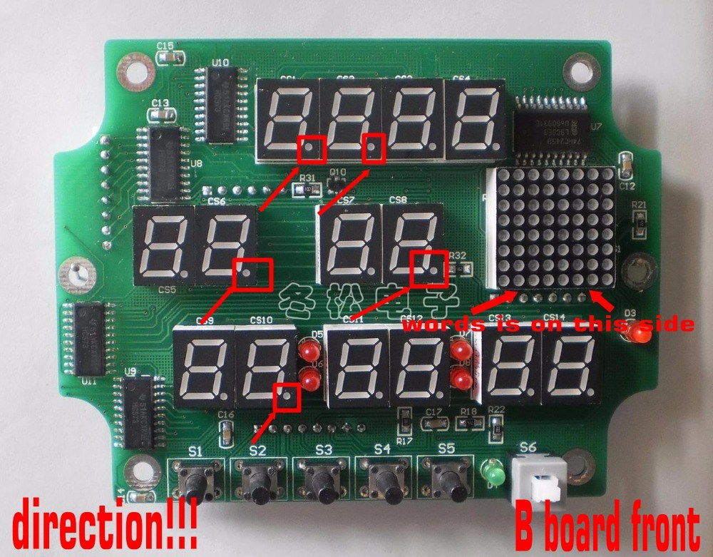
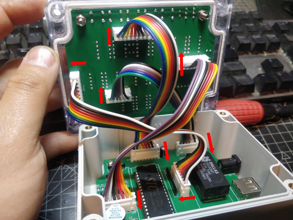
Wiring is very important
Note that the socket installation position is directional. The RED arrow in the picture indicates the direction of the socket notch.
Be sure to pay attention! ! !
If you don’t understand, you can send us an email to contact us.Email:bluefox911@163.com
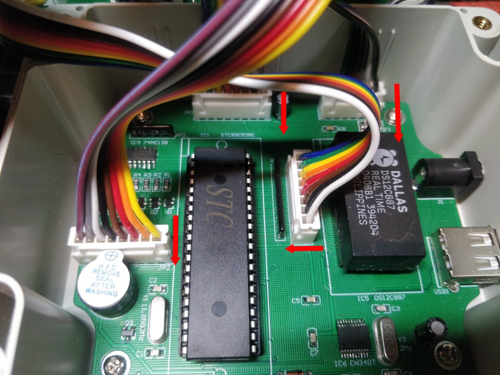
Pay attention to the installation position of the STC chip and clock chip, which is consistent with the picture below.
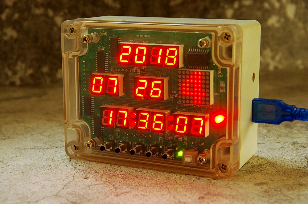
Connect the wires, install the four screws, and you’re basically done.
usb cable, 3.7-5v can be used
Finished! Enjoy!
4 评论
Can you provide an electrical hook up diagram for this clock? Please provide a link to download that
thank you
Hi Bill, I Googled them before assembling mine and the 12000 component was listed as used with USB ports, so I put it on that side of the board (right of image above). The other one (11.xxxx) went on the left. Worked first time!
These components (crystals?) have different numbers but I cannot read which one goes to Y1 and Y3 (please see picture with yellow rectangles identifying the parts from your Tutorial picture)
Are these actually the same component and it does not matter?
Please advise.
Thank You!
Bill
Can you post photos of wired with connectors.
I got the wires with wrong connectors