Diy table spark gap tesla coil -SGTC-type3

Diy table spark gap tesla coil -SGTC
5月 23, 2018
diy clock type1
10月 17, 2018
Help email:
bluefox911@163.com
!!!!!
In the DIY process, if you have any questions that you don’t understand, please send an email to our email address(bluefox911@163.com), the title says SGTC, we will reply you in the first time after seeing it.
Before you start making this project, we will tell you what this article is about?
1.Design ideas and principles.(about why we made and designed this equipment, as well as the principles and methods to achieve it)
2.DIY instruction(about step by step diy process )
3.Troubleshooting.(if your device is not working,how to find the bug?)
4.Free your imagination,more transformation and hacking.(Importand and fun,do not miss this!!!!)
1.Design ideas and principles.
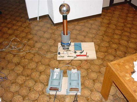
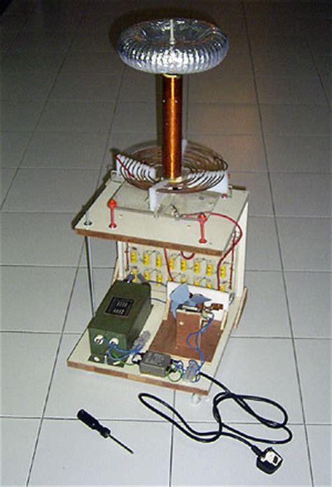
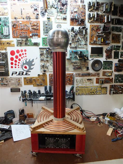
Before maybe you have see a lot of SGTC like these
Maybe you have seen too many classic Tesla coils
They are huge, expensive, dangerous, extremely difficult and time-consuming to make
Maybe you have always wanted to have your own Tesla coil because of curiosity, but for the above reasons, you gave up
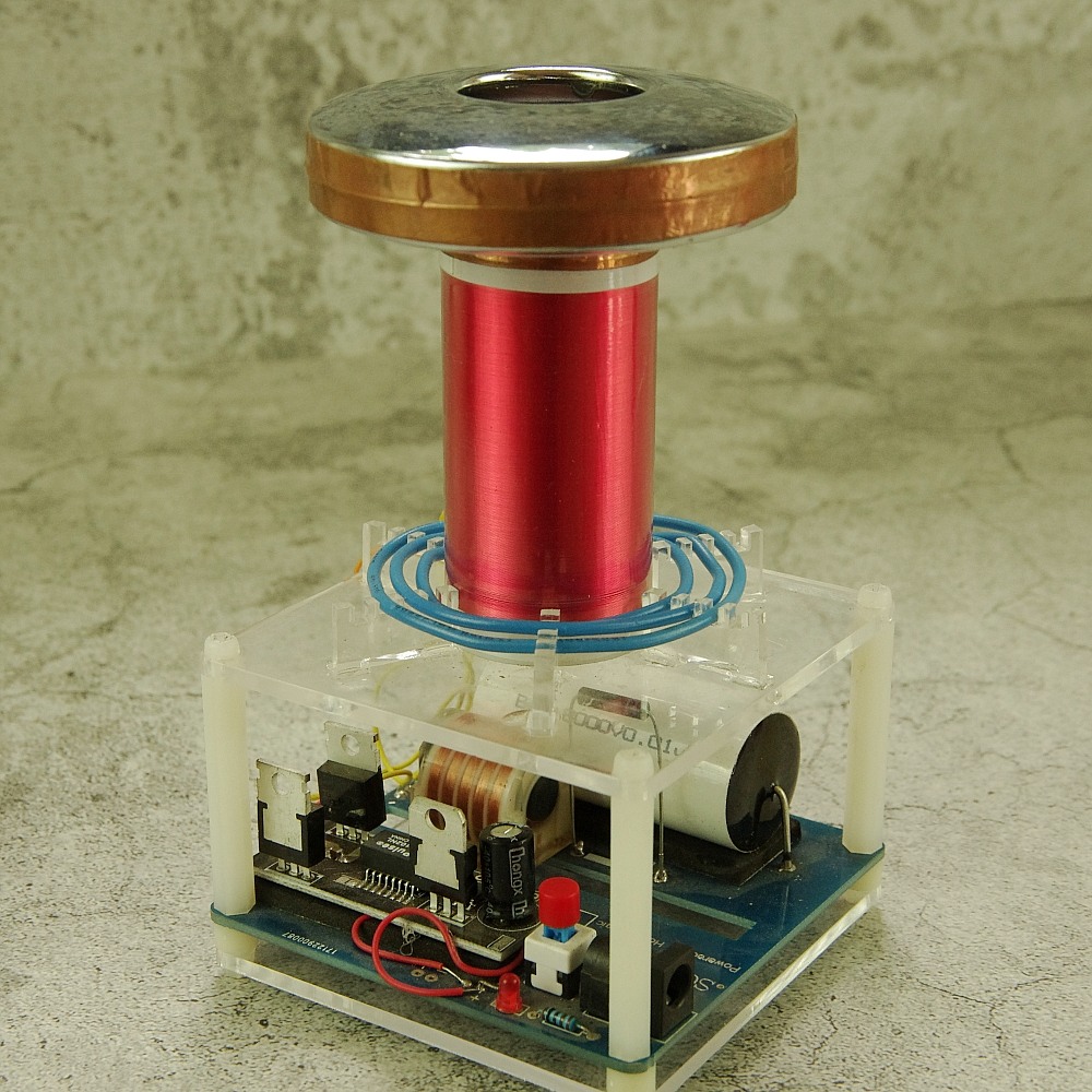
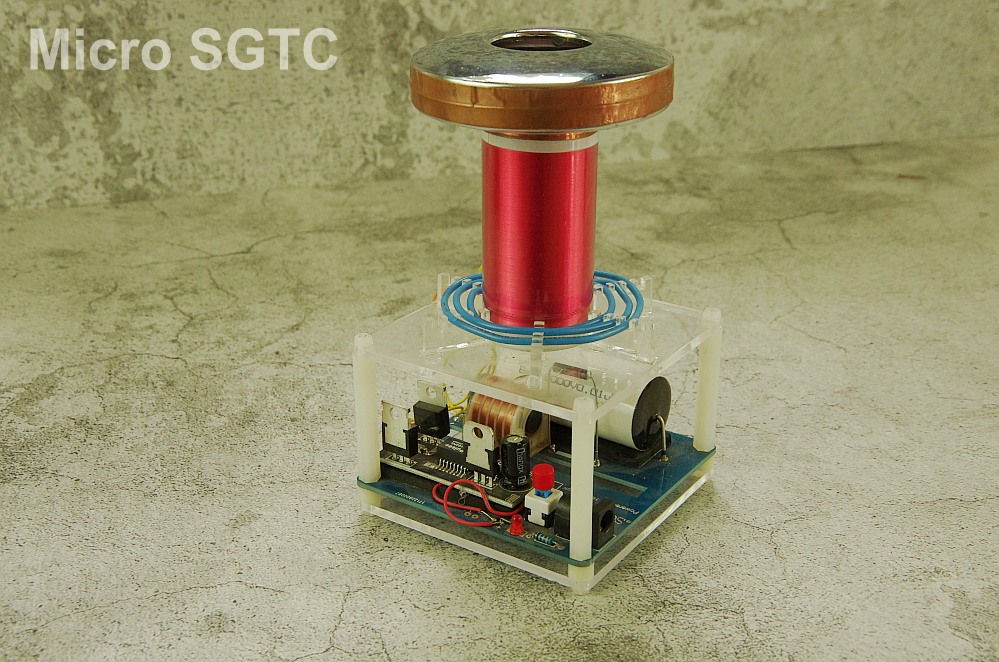
So we designed a very simple mini desktop Tesla coil, spark gap type, SGTC
The whole circuit adopts modular design, you only need to solder 9 components on the circuit board
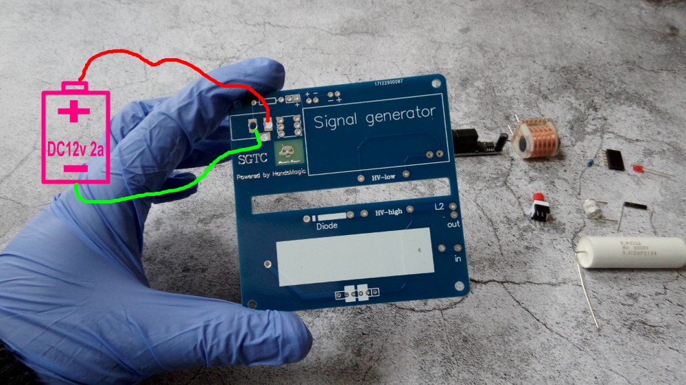
12v DC voltage, battery (12v 2a) can also be used.Any component failure can be easily replaced…..
Usually a SGTC contain High voltage signal generator,Igniter,Resonant capacitance and coil.The big SGTC is so danger and big because it use an AC power and many big Resonant capacitances,
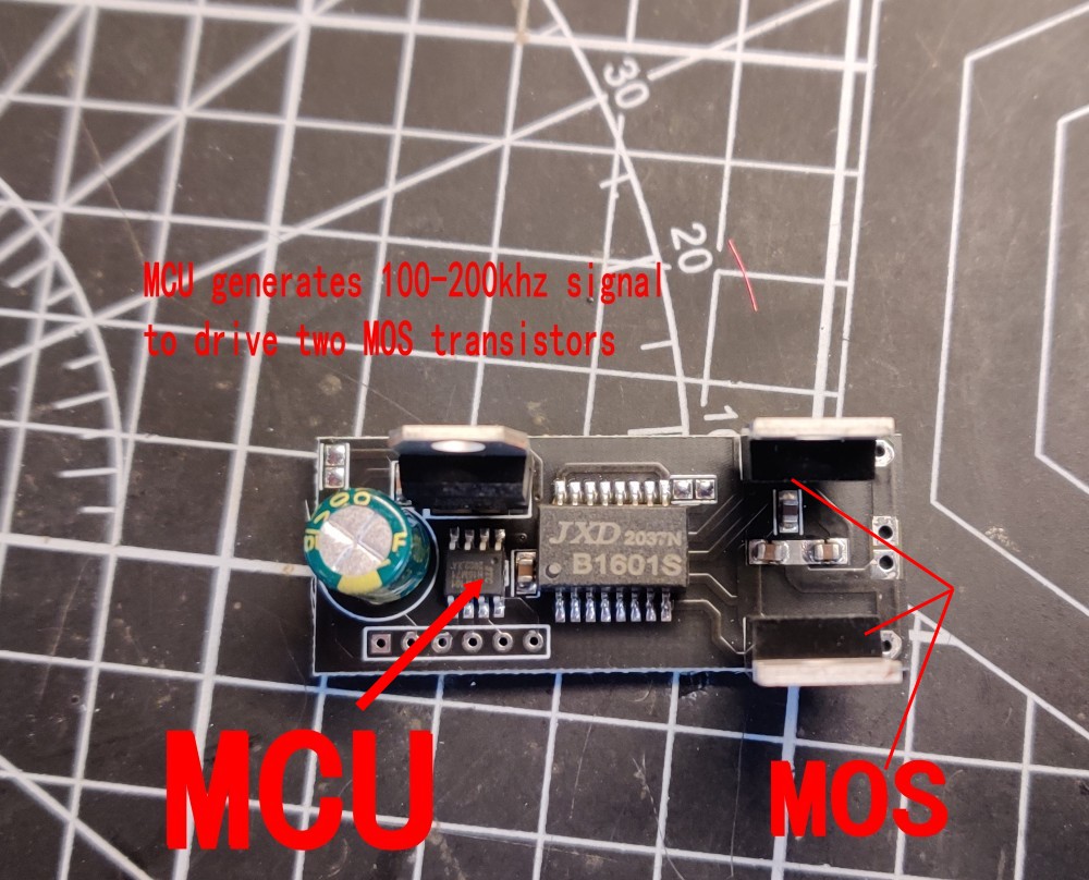
If we can get a high voltage signal from a low DC voltage, we can get close to our target.It seems that Inverter high voltage generator can help us
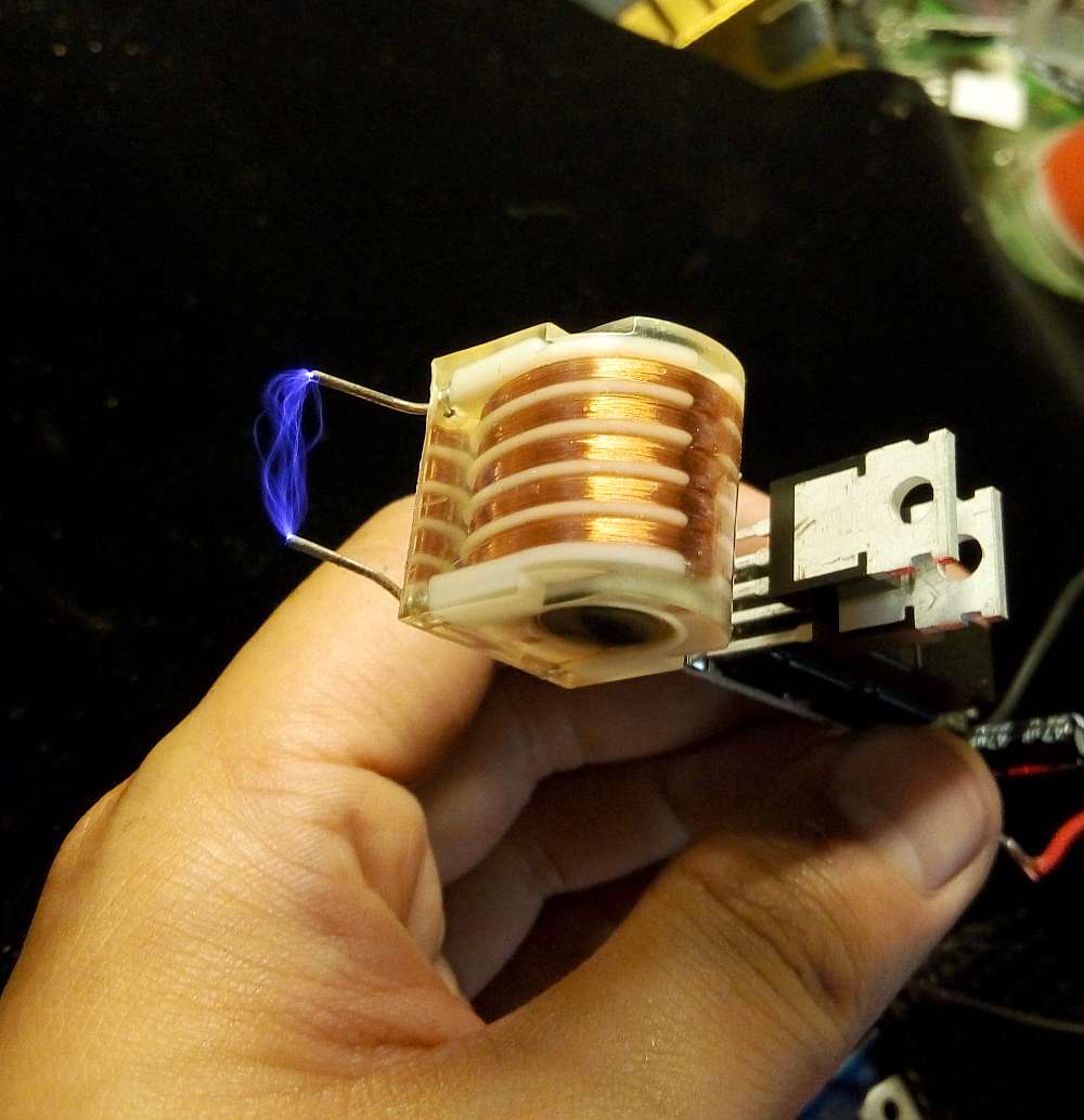
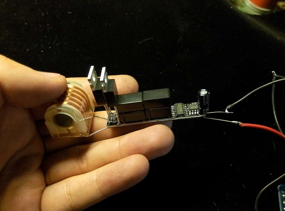
Here it is
(This is a Special high voltage module for igniter,
Input voltage 7~15V
Output voltage 15KV~20KV
(the picture is the older type,now what you receive is the new version)
then we need a small Resonant capacitance ,According to the parameters of our primary and secondary coils(calculation formula is on google) ,8000v 0.01uf is ok
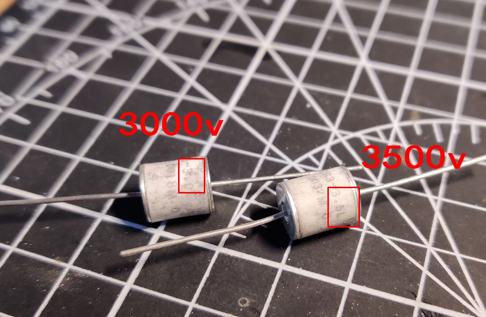
At last,interesting thing,the Discharge gap,we use Ceramic discharge tube,it has a small noise and we can choose 3kv-8kv breakdown voltage ,It is easier to damage,Belong to a consumable material, so it be designed to be replaceable And because of this you can choose to change the different breakdown voltage according to your own preferences, and there will be a different effect.
another DIY discharger
2.DIY Process
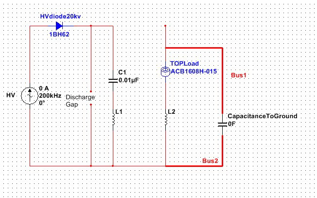
Schematic diagram
OK,let us start making it
Step1
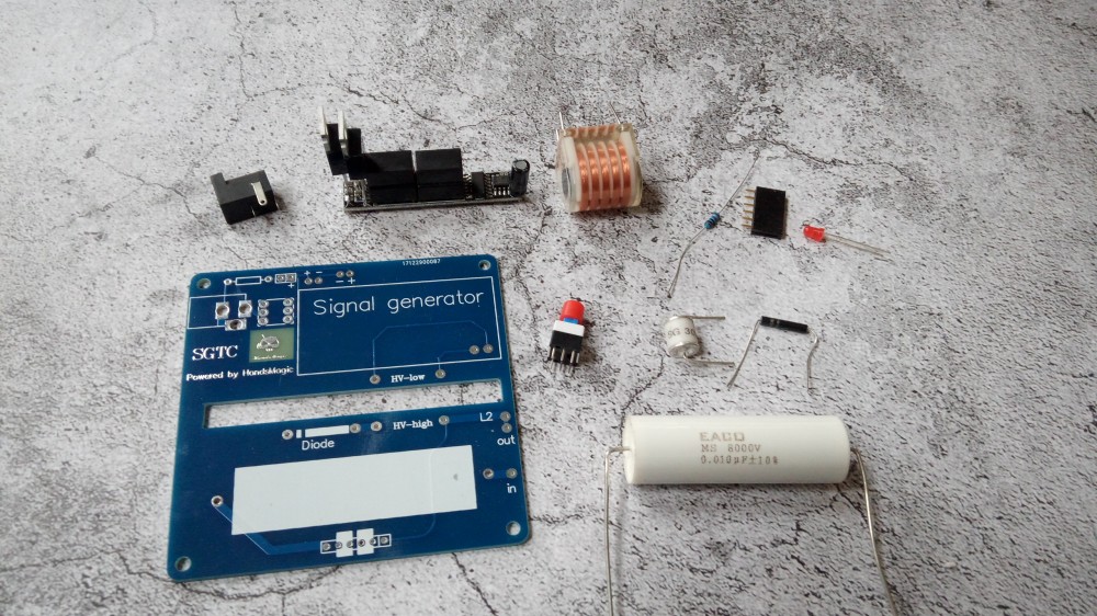
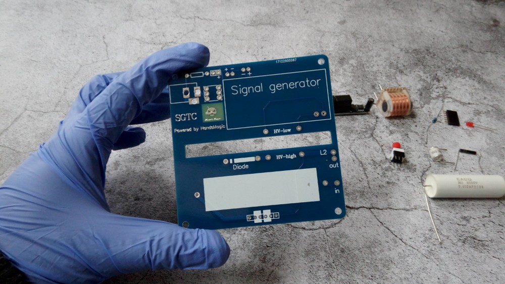
Scattered parts
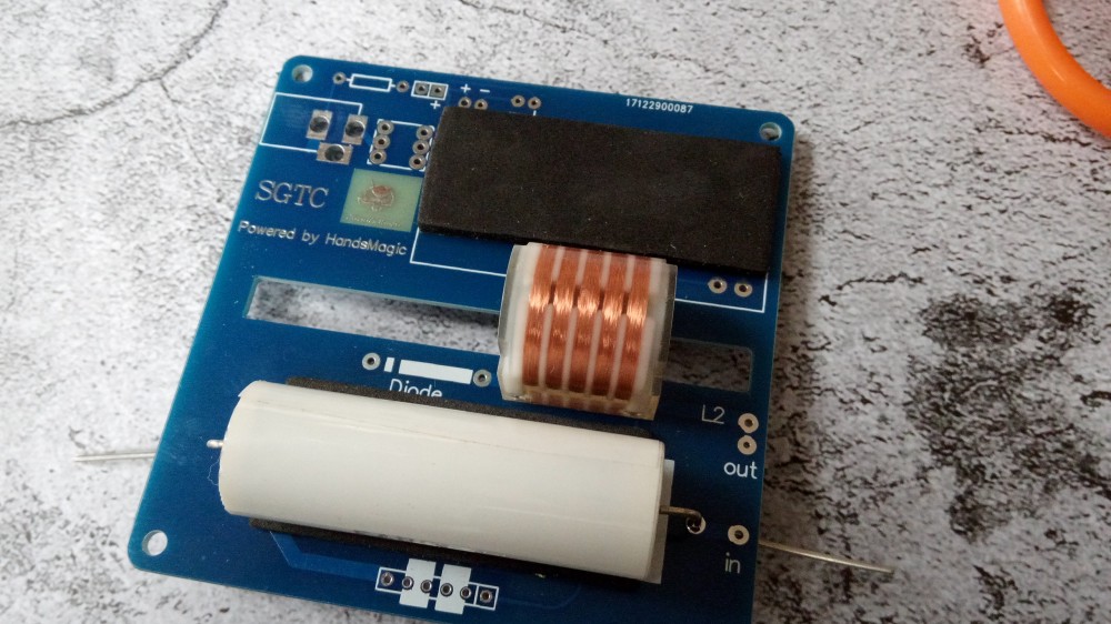
Foam is buffered at the bottom
step2
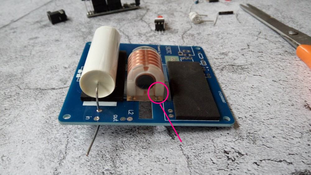
The transformer coil needs to be installed according to the picture, and the rough copper wire is the primary position.
Please look at the annotation on the picture
step3
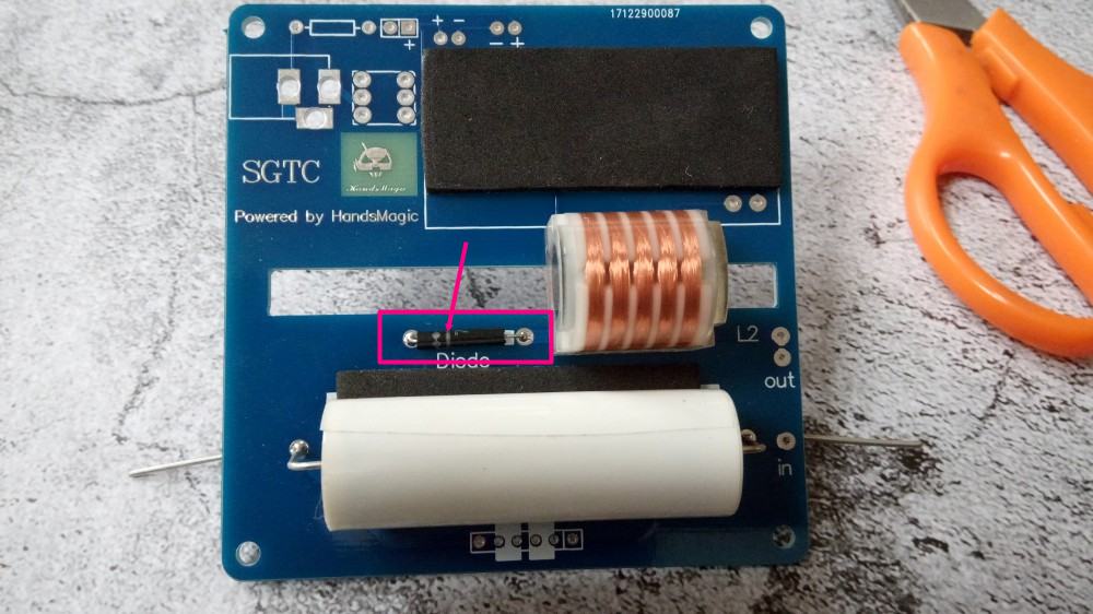
High voltage diode
step4
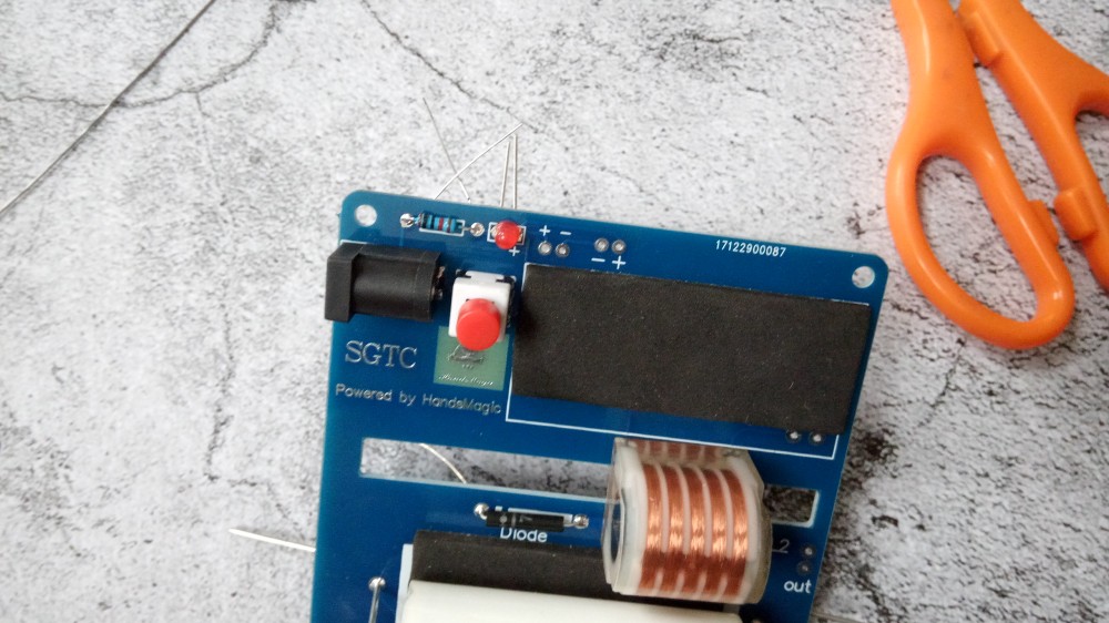
Power indicator lamp,led long foot is +
step5
Power socket and switch
step6
Igniter socket
step7
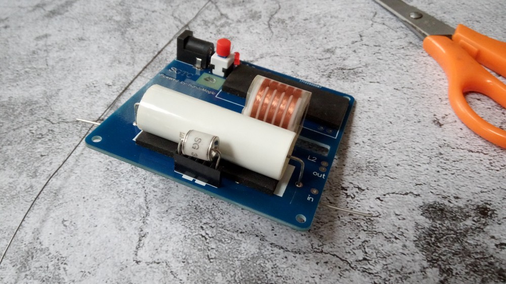
the Igniter
step8
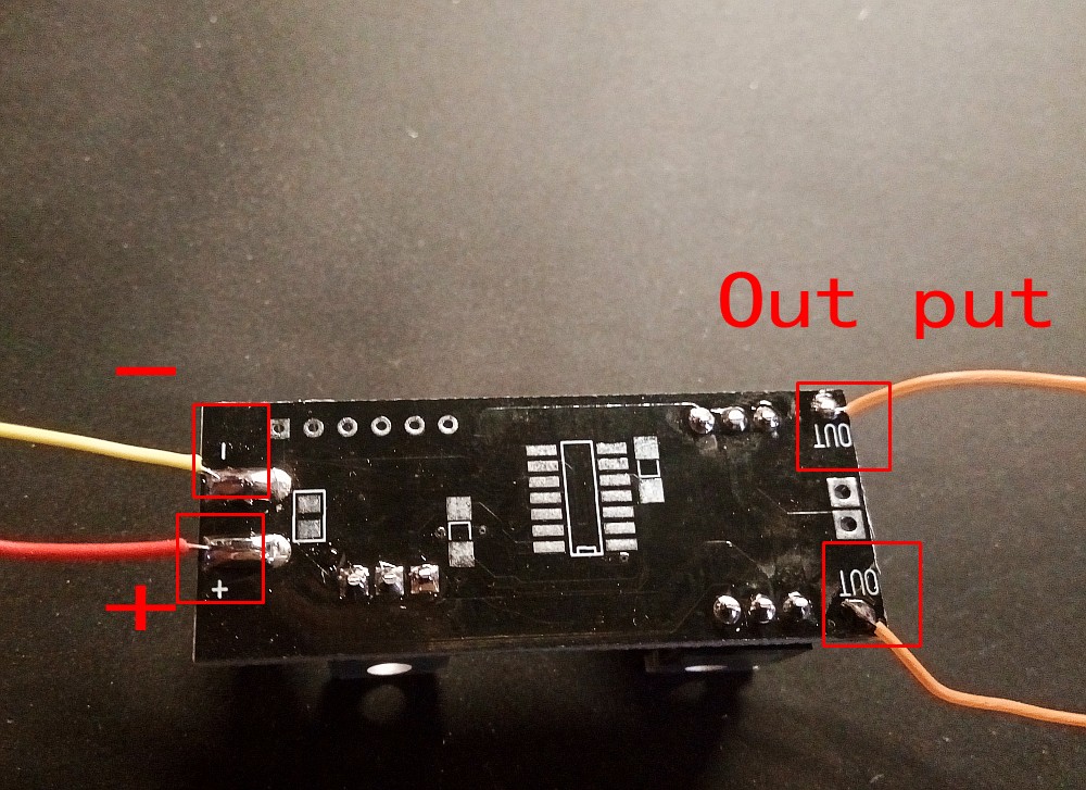
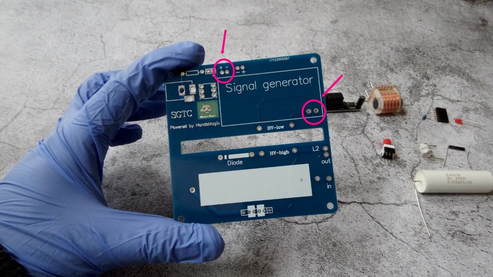
High voltage signal generator(in the back there is label “+”,”-” and “”out“”)
red wire is + yellow wire is –
soldering to the right place marked in picture below,on the board you can see “+” and “-”
ok,the board finished
step9
now need connect the Primary coil and secondary coil to this board
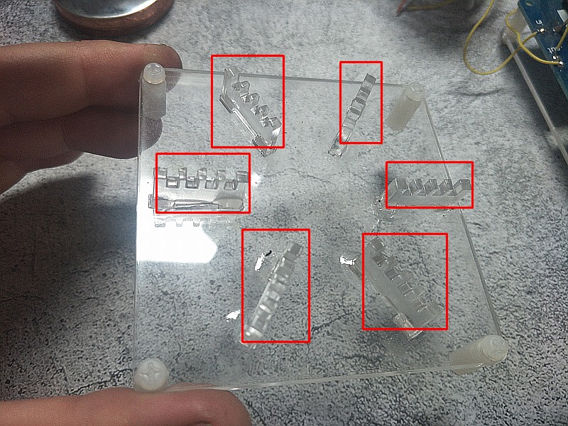
first glue the bottom shell
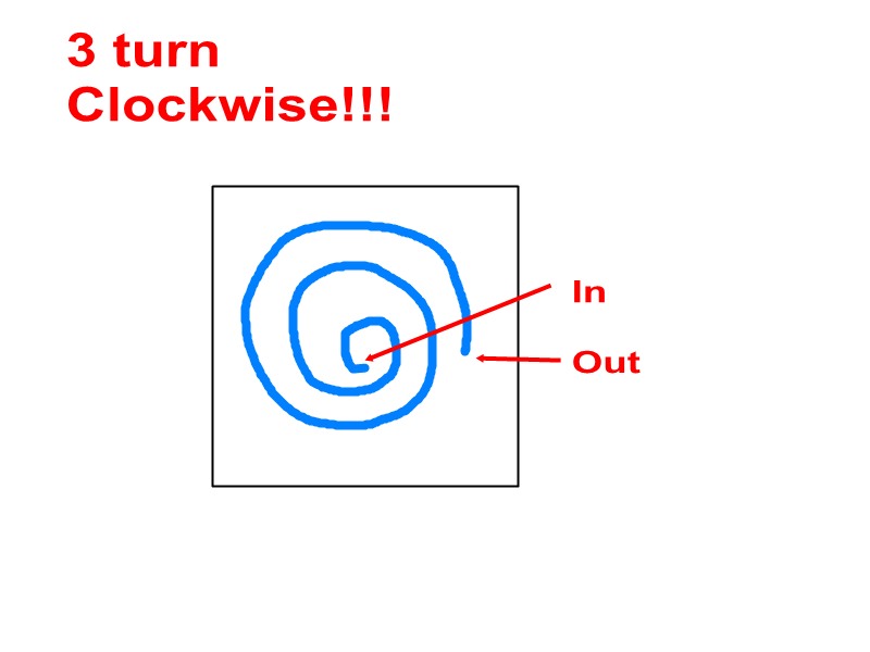
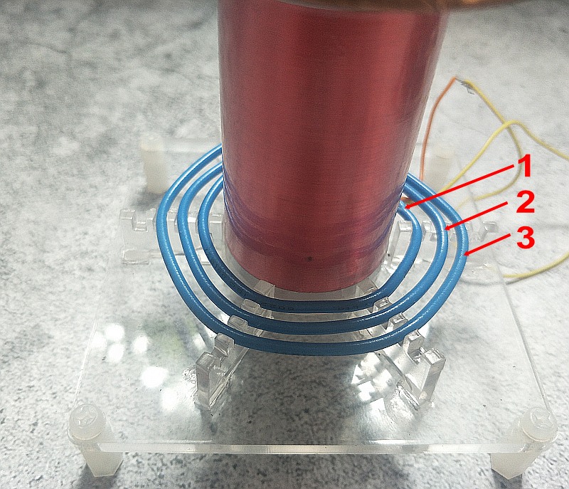
The primary coil winds three turns(Although the bottom is reserved for 4 turns, but please winds only 3 turns,and must Clockwise)
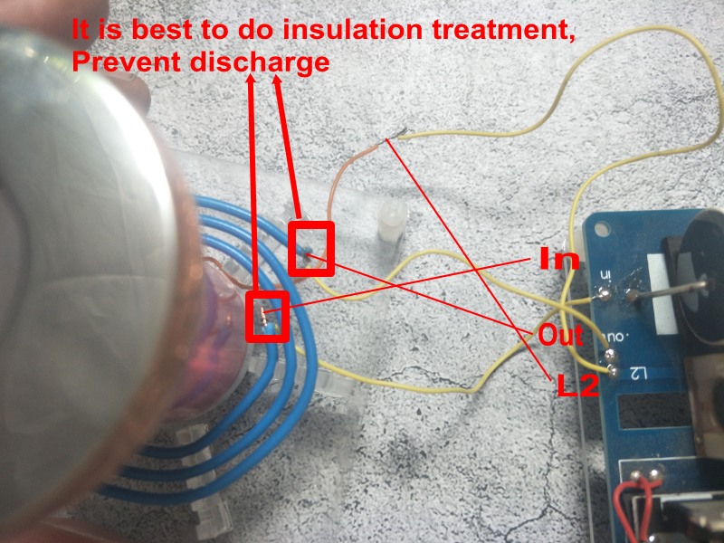
Now solder the “IN” “Out” “L2”
The soldering place is best to do insulation treatment,
Prevent discharge(Cover exposed wires with tape)
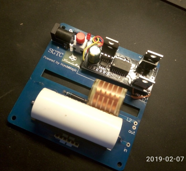
Ok,finished all the soldering.
About the power suply:
you can use any DC12v power suply(make sure the out put current is 1A-2A)
For example:
if you don’t want to use the plug,you can solder two wire directly to the board,and connect them to your DC12v power
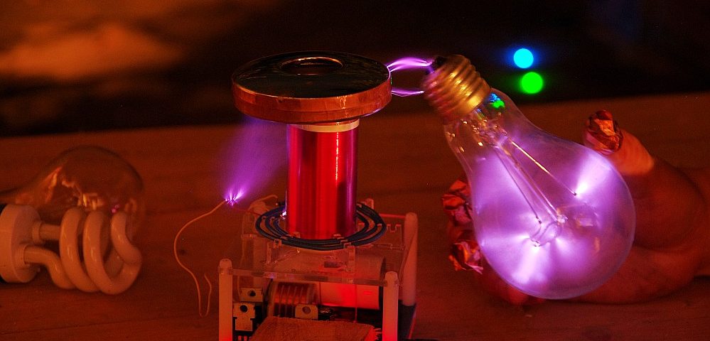
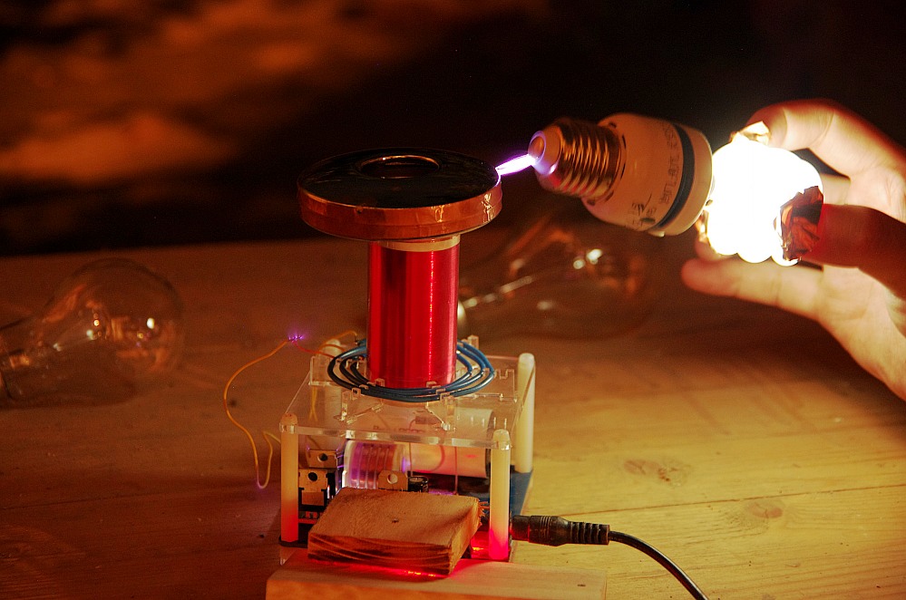
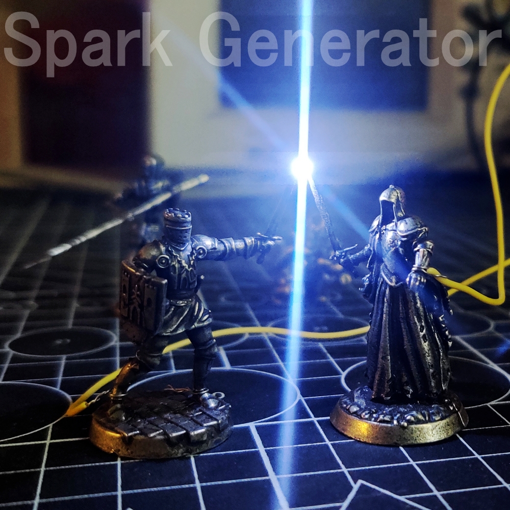
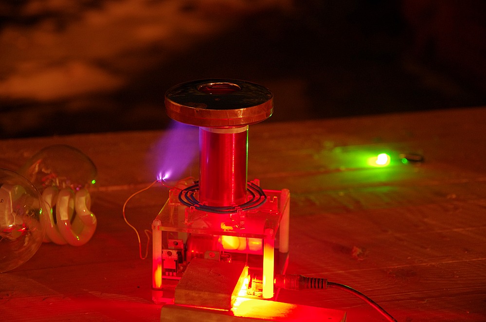
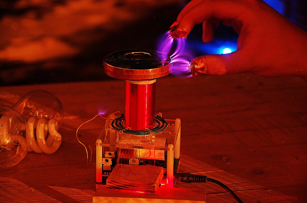
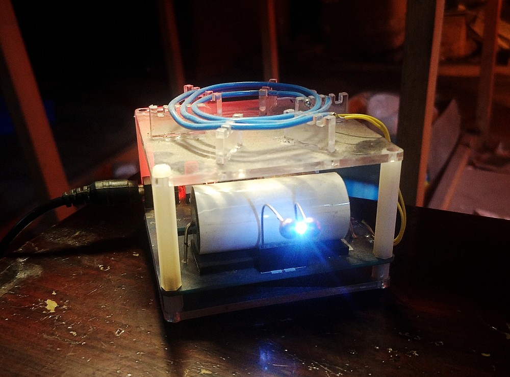
ok,all is done,12v dc power,you can use it now(plz use it in dark place,you can see the spark and arc)
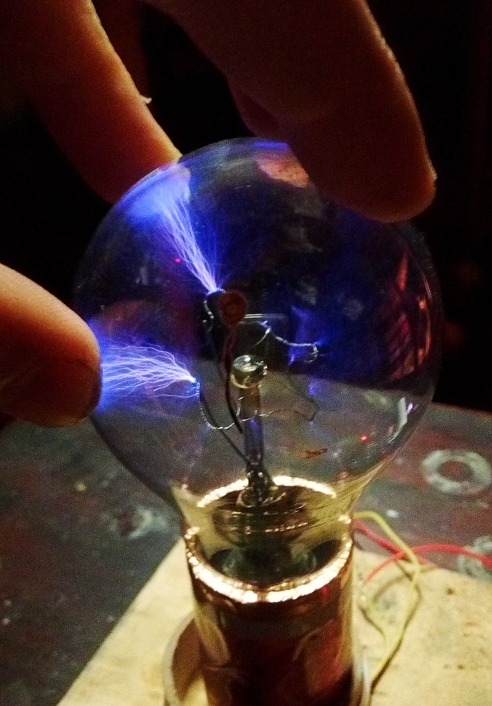
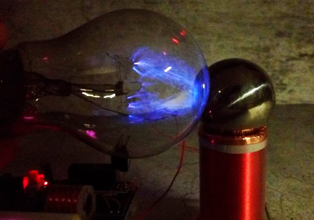
find a Incandescent lamp
3.Troubleshooting
If the system does not work with the correct welding,
How to find the damaged component?
1.first check your power suply
Tesla’s work will cause interference and may directly damage your power supply, so check the power supply first if it is not working
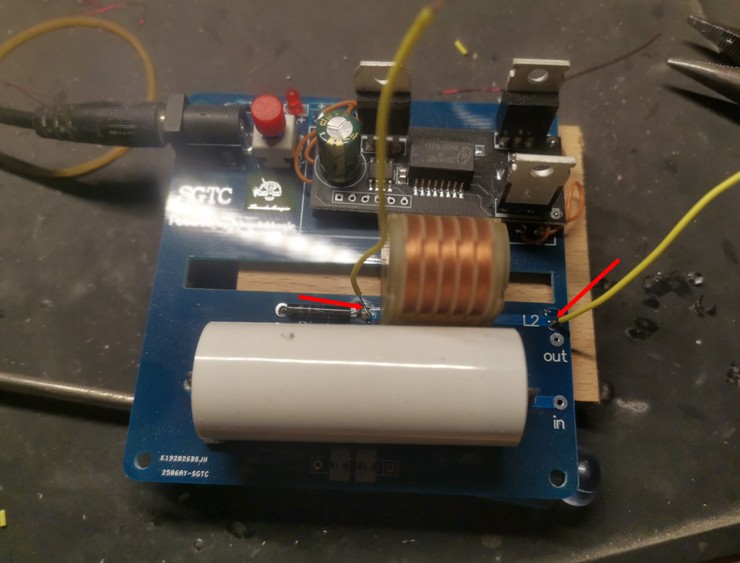
2.Make sure the power supply is good, the next step we check the black board is good or not,you need to weld two wire,look the picture below
Look picture,distance less than 4mm,then power on
If there is spark like picture,that means the board is good
3.check the diode and Capacitance
you still need two wire,weld them like picture below
If there is spark,that meas your board is good,you just need change a Discharge gap tube or your power suply was broken
Hacking
ok,now you got a SGTC,but the journey has just begun………
In design, we have separated the high voltage signal generation circuit and the power resonance circuit, so how do you play it? You can replace any independent part. As long as you understand its principle, you can try to use your own DC high voltage inverter to drive the power resonant circuit, or make a power resonant circuit yourself, drive it with our signal generating circuit…
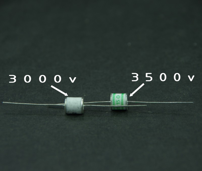
in the packet,there are two different Ceramic gas discharge tube,the white one,breakdown voltage is 3000v,and the green one is 3500v,different breakdown voltage will affect the charge and discharge frequency of the capacitor, thus changing the operating frequency of the entire power circuit, the closer the frequency is to the resonant frequency, the energy can be maximized.so you can try yourself to see what is the difference of this two tube(Ceramic gas discharge tube is very easy to break, if it is broken, please replace it, we sell it in our store )
As a maker, we should learn to understand the essence through phenomena.
It is not must to use ceramic discharge tubes,if we use the Classical ball-gap discharge,what will happen?
Taking action is better than just thinking,let’s do it!!!!!
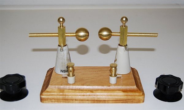
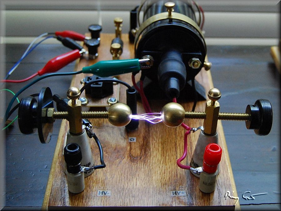
The Ball-Gap Discharge
Ball gap discharge prevents tip discharge and allows concentrated energy release……..
(The above picture is from google, If we infringe on your copyright,Please contact us to delete!)
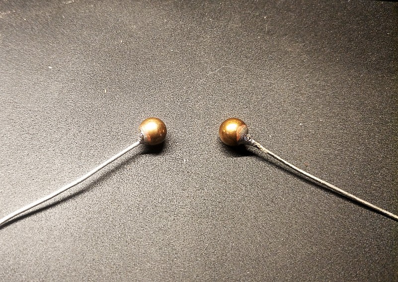
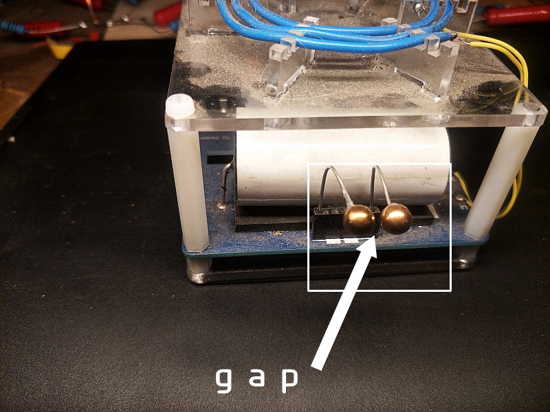
Make a ball-gap discharger
For easy drilling,
Use brass balls,
Because brass is soft and easy to drill
drill
It is easy to weld a wire by drilling a hole
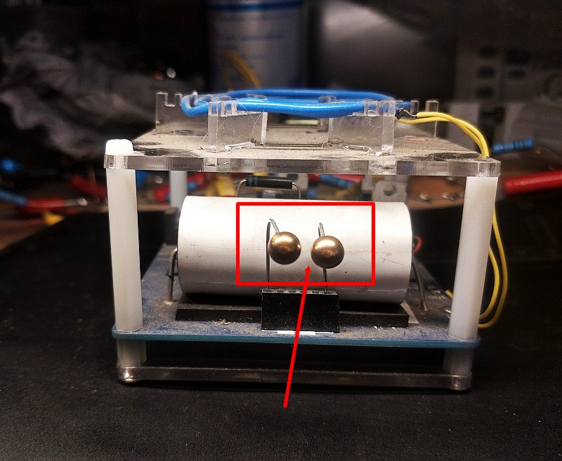
A pair of ball gaps was made successfully
As for the size of the gap, you need to experiment.
Different sizes will cause different discharge frequencies ……..
Many parameter can work,The difference is only whether it is closest to the resonance frequency of the system
Don’t forget, we are making SGTC!
In order to obtain the most spectacular discharge effect without changing the input power, try to make all parameters close to the theoretical calculation.
This is what a maker should do, isn’t it?
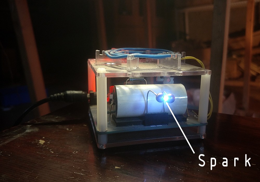
The ball gap discharger has been completed,but after we soldering the Secondary coil ,Unexpected situation happened!!!!!!!
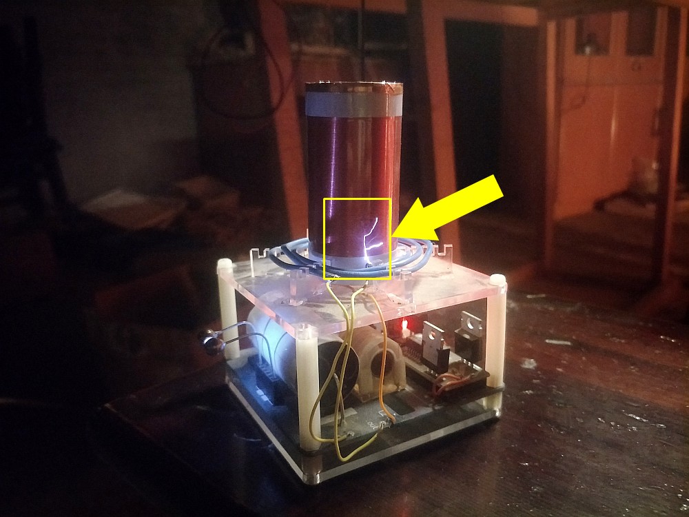
An arc is generated between the primary coil and the secondary coil
It seems that the energy is enhanced, but the secondary coil is not insulated enough.Because only a thin piece of plastic is used to cover the secondary coil,It seems that we need to enhance the insulation strength of the secondary coil.
Brushing epoxy is the best way, but I am too lazy and don’t like the feeling of slimy, so I try to find a big heat-shrinkable tube, I hope that its insulation strength can meet the requirements.
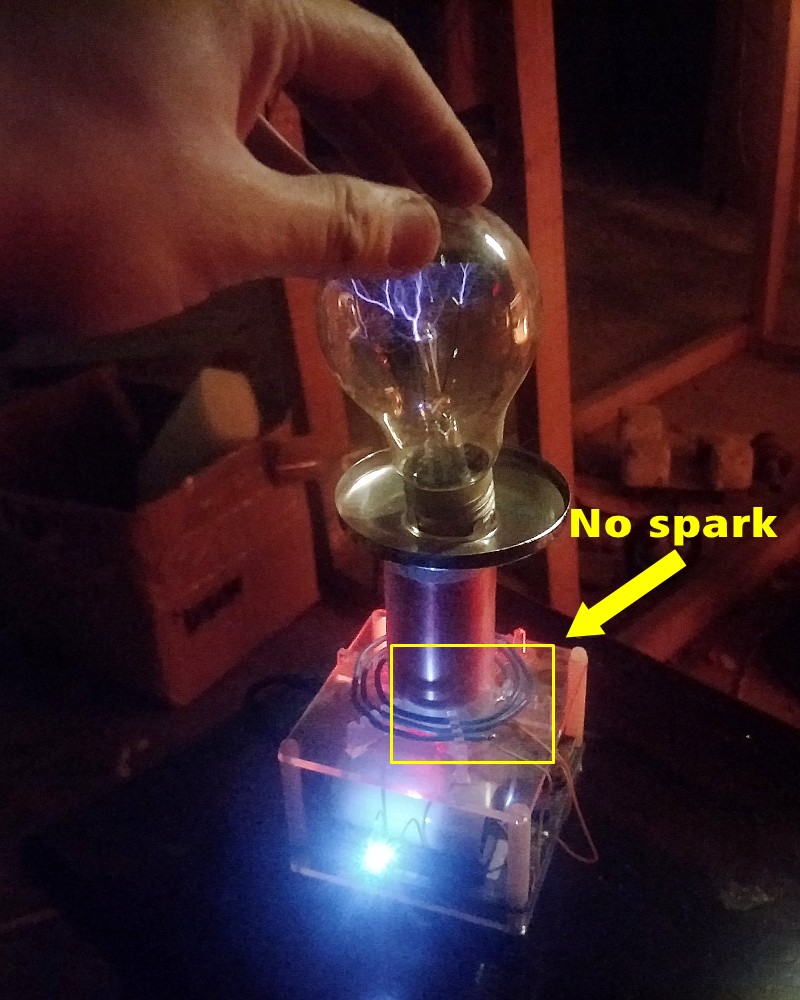
It looks good, there is no spark between the primary coil and the secondary coil.
Ok,now we finished this transform, got some trouble, but we solved it.
We just made a demonstration, hope you like this project.
Next, I will show you a wonderful DIY
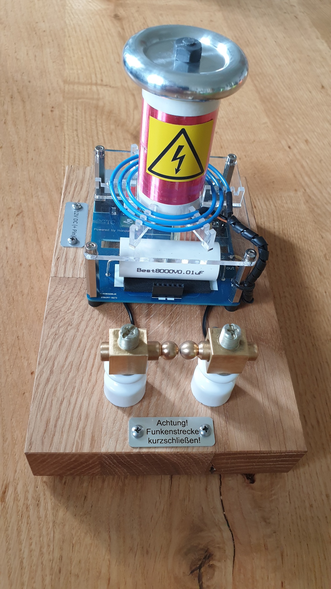
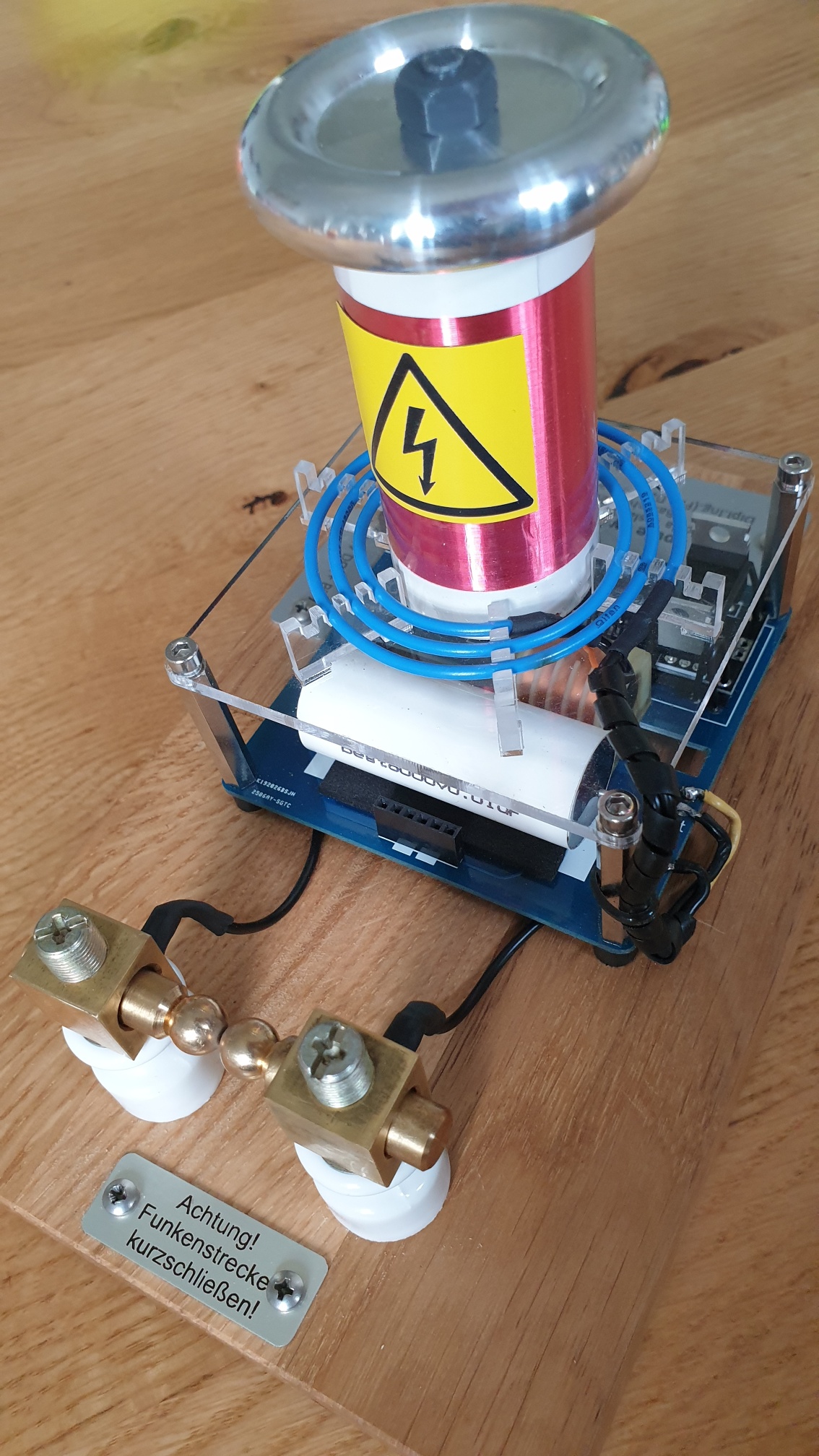
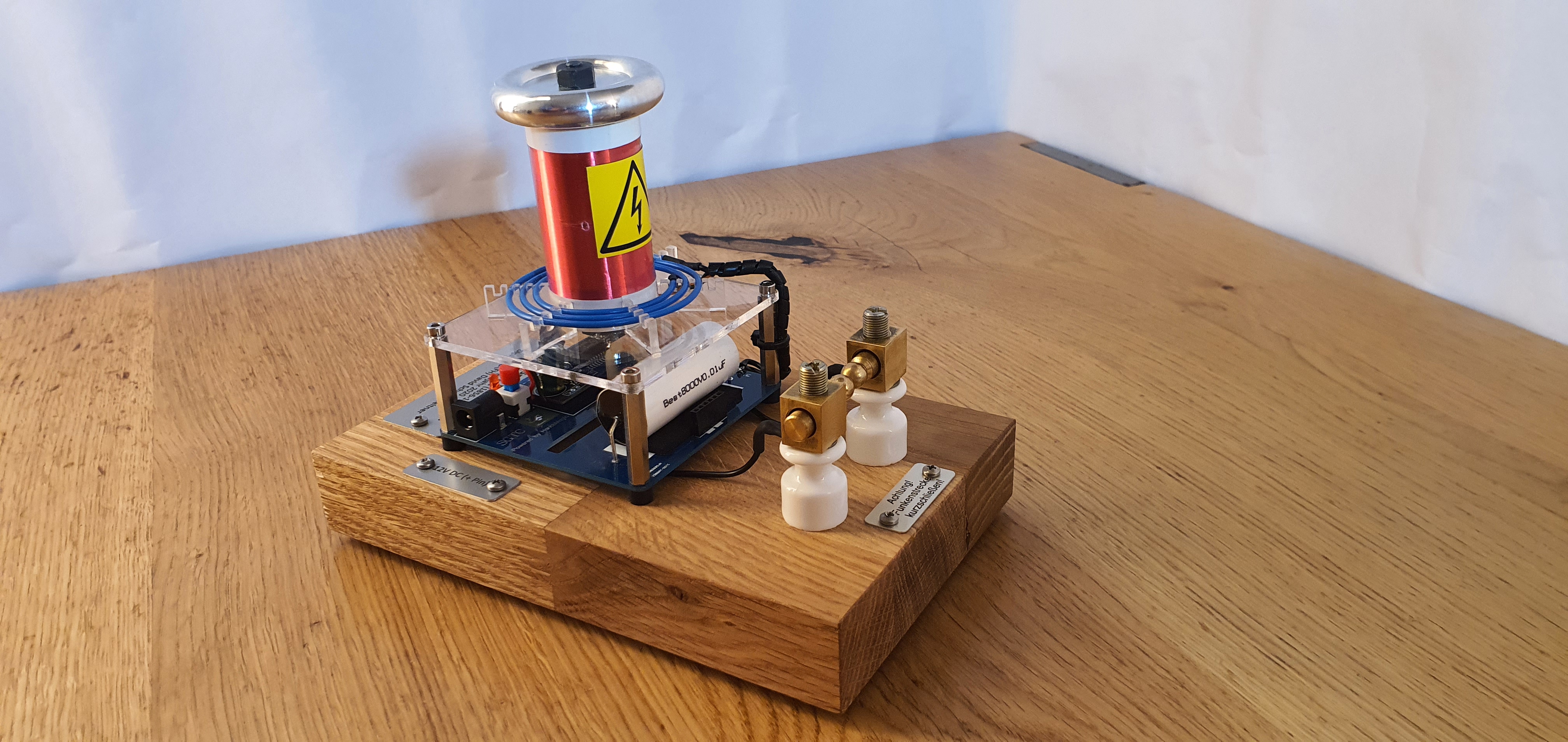
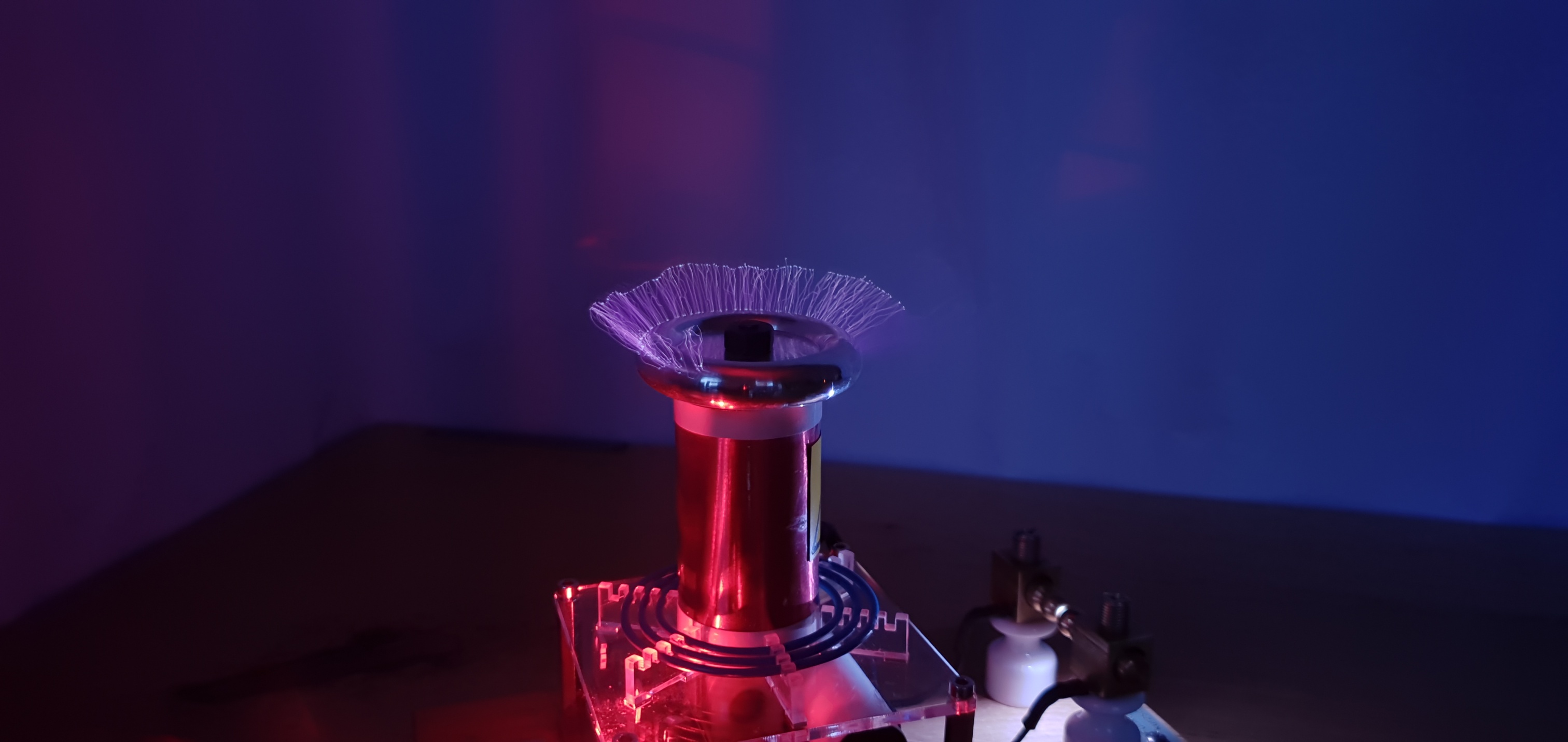
1.Designed by David Stefan Schacherleitner
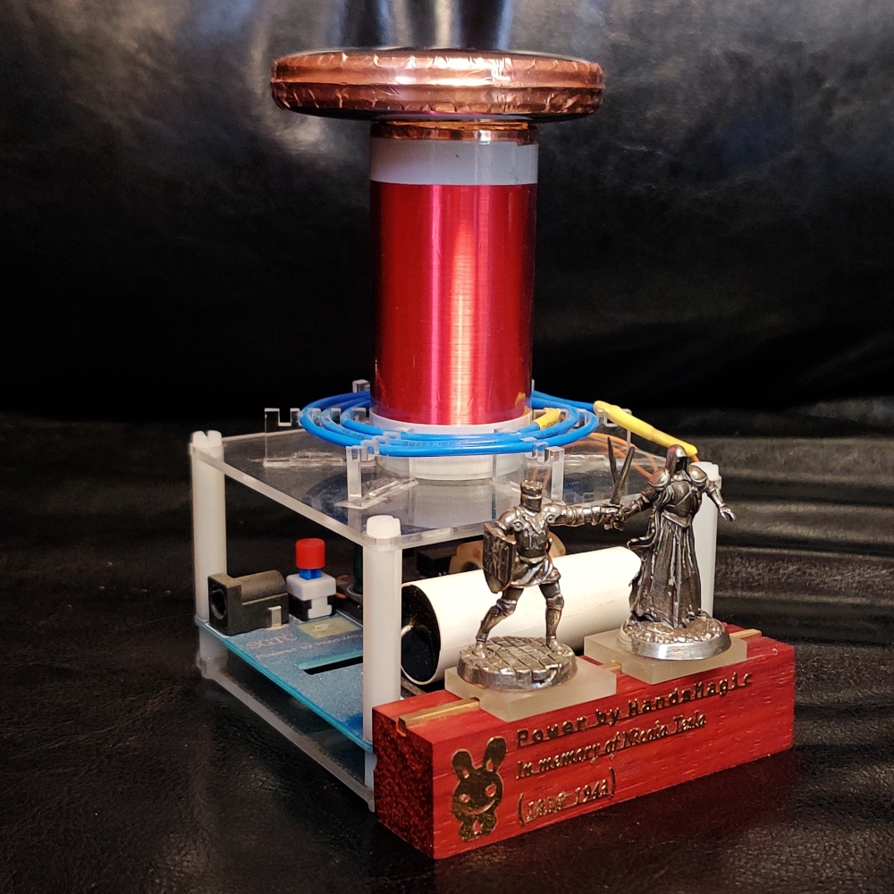
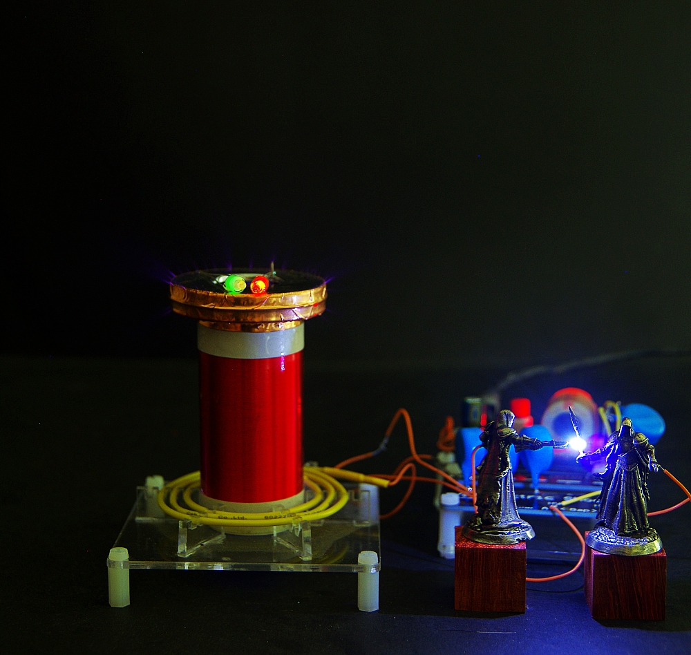
2.
At last,Enjoy!
Next article, we make a ball gap sgtc







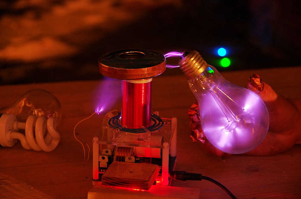
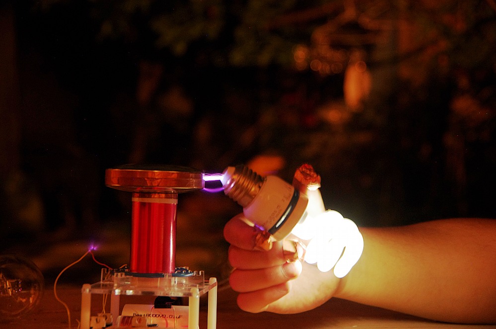
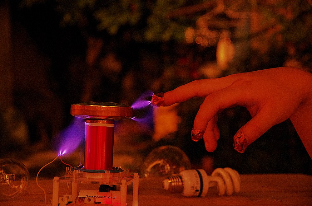







7 评论
Hello,
I just built my tesla coil and overall it’s very cool
However, I am getting a pretty visible and large spark at the ceramic discharge tube (I am using the 3000V tube).
I put some electrical tape around it, but should i do something else to make it more safe?
Thank you!
Maybe you can add a discharge resistor?
We need some more specific information about the parts of the mini tesla coil
– How many windings has the secondary coil?
– How many windings has the transformator and what is the voltage that it outputs?
– What are the specifications of the diode?
– What are the specifications of the high voltage signal generator?
– What is the resistance of the resistor?
– What is the resistance of the led lamp?
We would appreciate it if you would help us. We are working on a school project.
Thank you.
Regards
Marcin and Faris
is an arc supposed to also ocur in gas discharge also?
what do you mean?
您好,我最近买了一个迷你SGTC。
我想知道谁是SG 302的火花隙?我想订购替换品。
you can send message in our shop,we will contact u