

Make a simple Bluetooth4.0 control robot

Mendocino motor type3
11月 24, 2017
make a Mini table SGTC tesla coil Spark gap Tesla coil
2月 10, 2018this is a simple robot project
here are some Features:
1.Andriod apk
2.bluetooth 4.0 moudle
3.AVR attiny13 MCU(9600 baud rate communication with the bluetooth moudle)
My plan is use the Andriod phone send the command,it is like “A”(0x41),”B”(0x42),”C”……….,then the bluetooth get this code,Transfer to the AT13,AT13 decode the command,like
if(A)then TURN LEFT
if(B)then TURN RIGHT
if(C)..........
so the robot can move.......
i think the hard parts is write an apk run on andriod,maybe also a little hard write a 9600baud rate communicate
program of the AT13,but Practice makes perfect,right?it just take some time
the point of the apk,is getting the characteristicof the bluetooth4.0,it is like a door in a building,so i have to handle some array,one dimensional array,Two dimensional array……… but after fix them all,See the dawn
we provide source code and download apk at end of this page
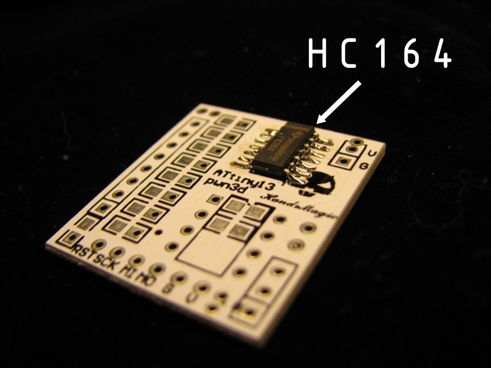
Step 1: Use Hc164 Extension IO
the Attiny13 has 5 IO,but one for RST,another for the Bluetooth moudle,only three left,so we use a HC164,it Occupy 2 IO,But provide 8 IO
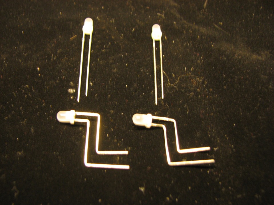
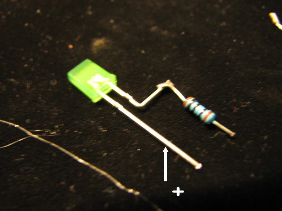
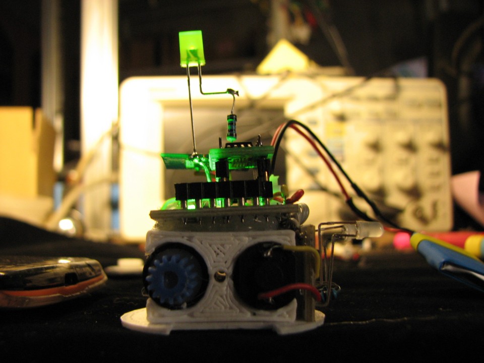
Step 2: LED,IC Socket and the Power Socket
The LED positive pole has been marked on the picture
If you can’t distinguish between its positive and negative poles
Please use the multimeter to measure

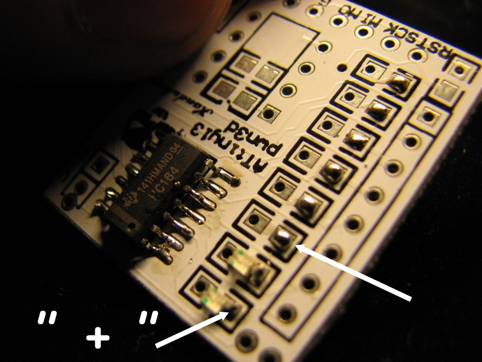
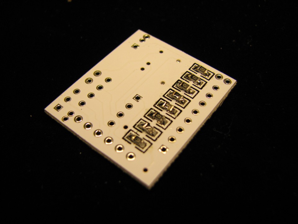
on the back is 1K resistance
They decide the working current of LED


Step 3: Program Upload Socket
this is for upload program on the AT13,Six holes for VCC GND MOSI MISO SCK RST

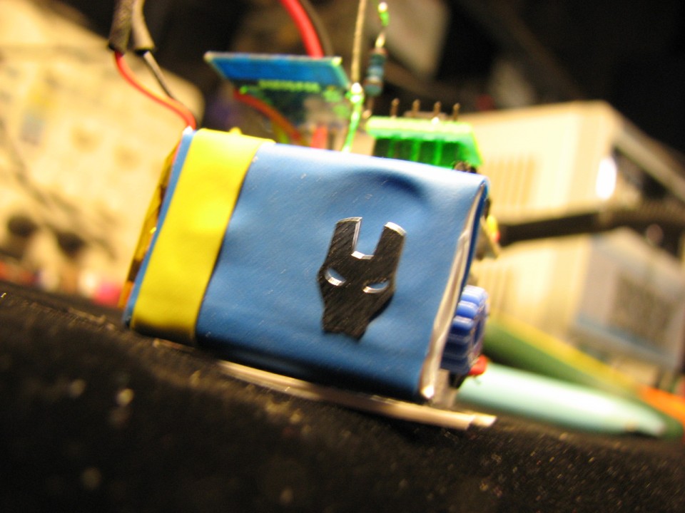
Step 4: Battery
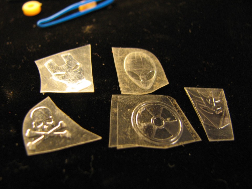
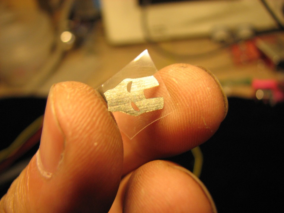
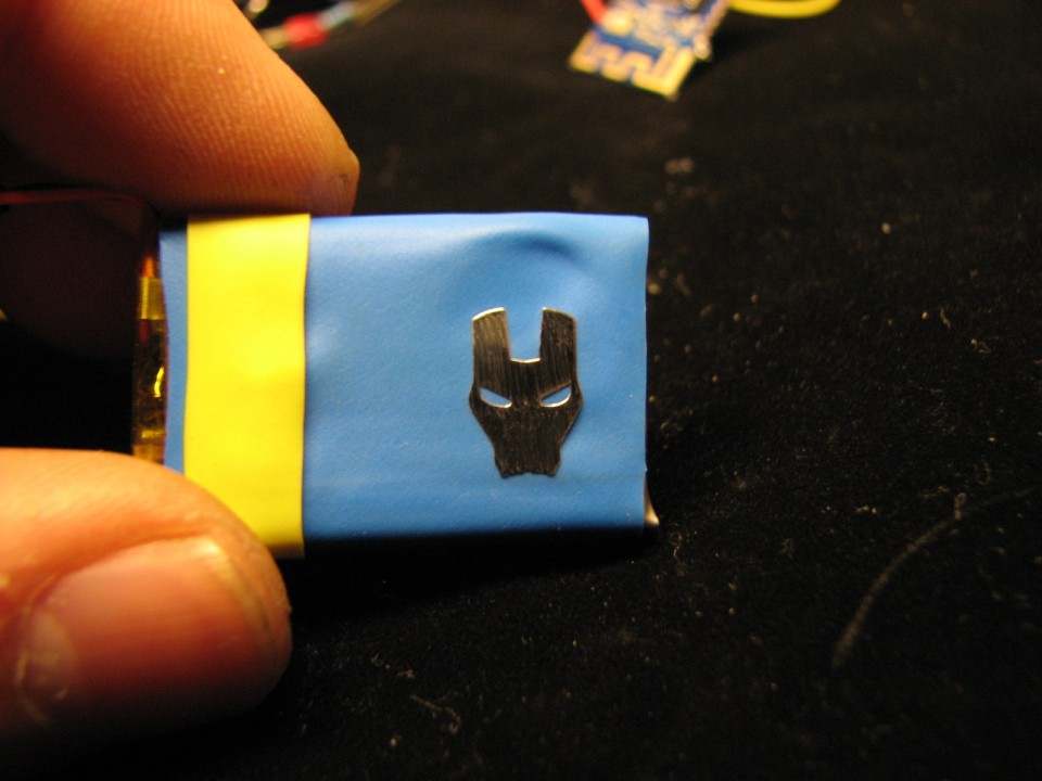
Colorful heat shrinkable tube,Hot air heating with electric hair dryer
we havs some Metal decorative adhesive,we choose the Iron Man,because the robot is called “T_man”


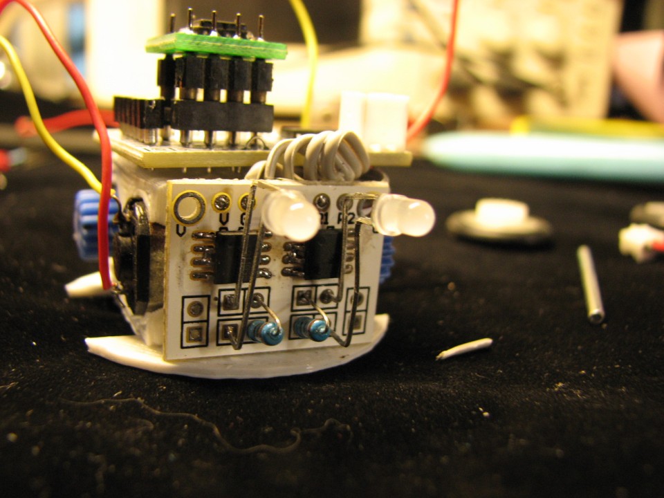
Step 5: First Test

first put the AT13 in the socket,Please note that “1” position
then power on ,the Fifth led is on,that means it is ok
Step 6: Motor Drive Board
L9110
Bending Led foot like picture,Resistance in the middle, 100 ohm
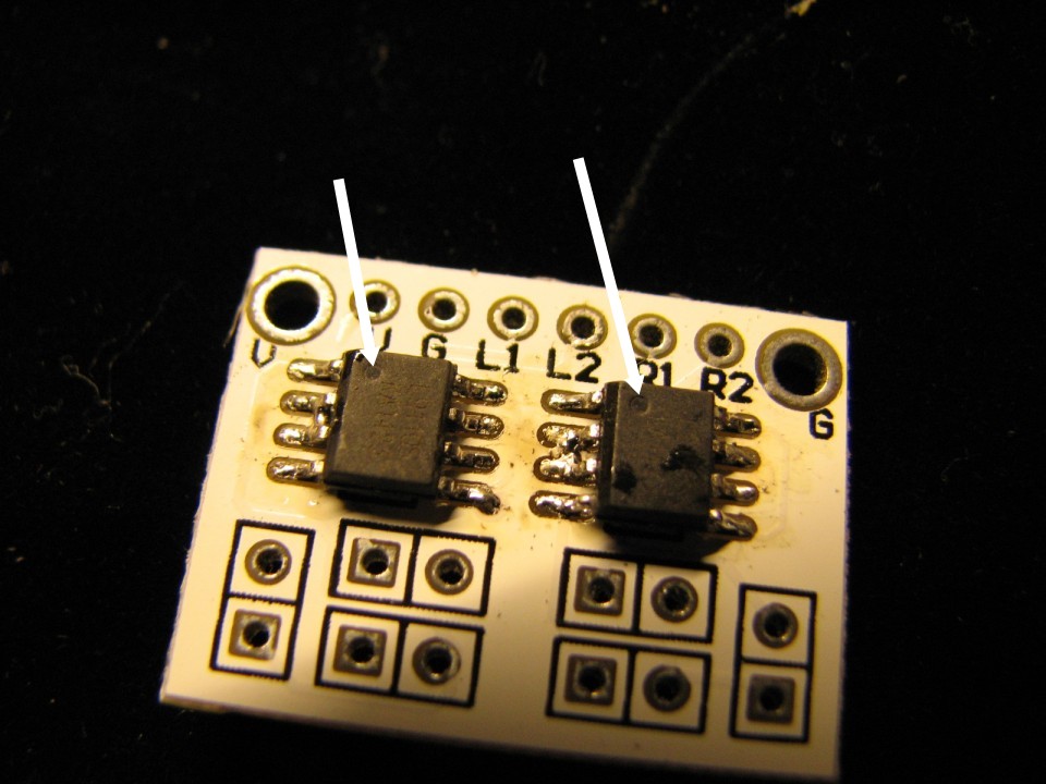
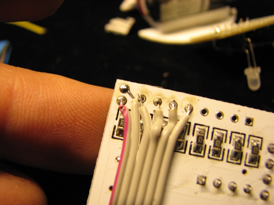
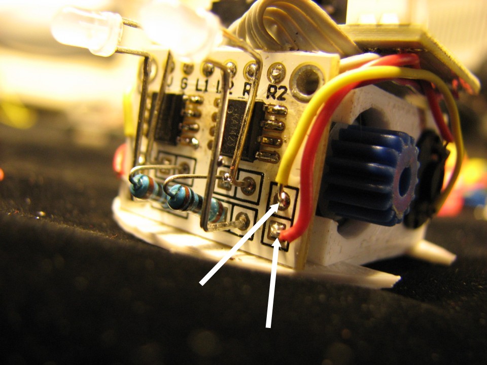
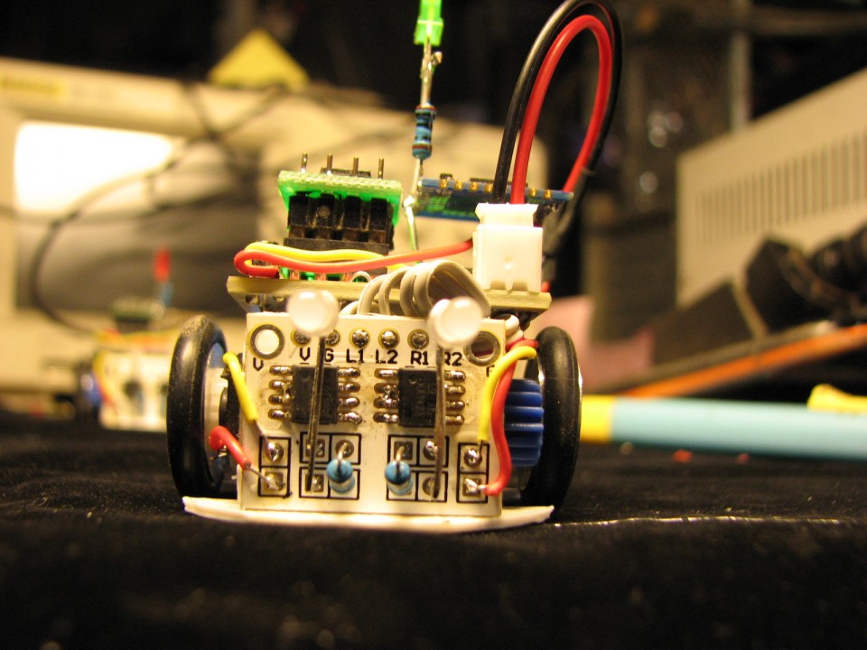
Step 7: Welding the Wire on the Mother Board
VCC GND L1`L2 R1 R2
(L1`L2 R1 R2) are four single to control the motor Positive inversion

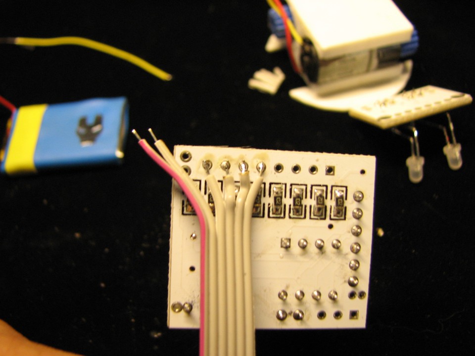
 、
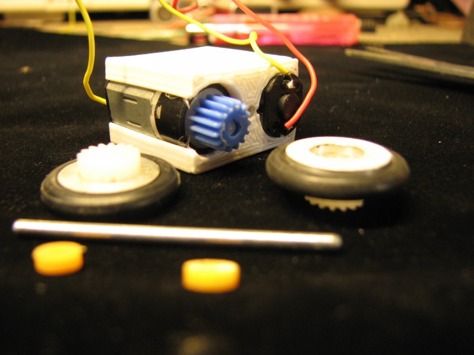
、Step 8: Chassis Assembly
Glue!!!!!!!!
the mother board I use hot melt adhesive,In order to avoid the glue temperature is too high, melt the wire, I will wait for it to cool a little
the motor drive board is not glue yet,just for Determine how long wires stay

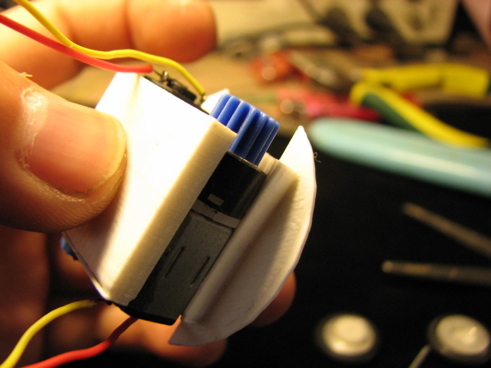
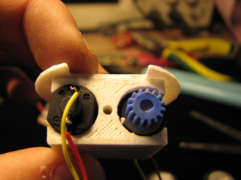


Step 9: Connect the Motor Driver and the Mother Board
Six wire to the right place
then glue the motor driver on the front like picture,be careful that the Solder joint do not touch the metal of the motor,because it will short circuit,i just give more glue,so it can Separate them
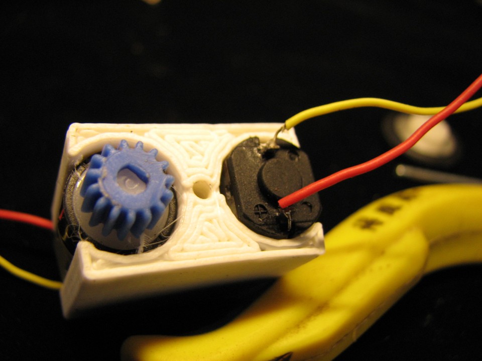
At last,welding the four wire of the motor,do not care about the positive and negative,if not right,after welding the bluetooth moudle,we can adjust

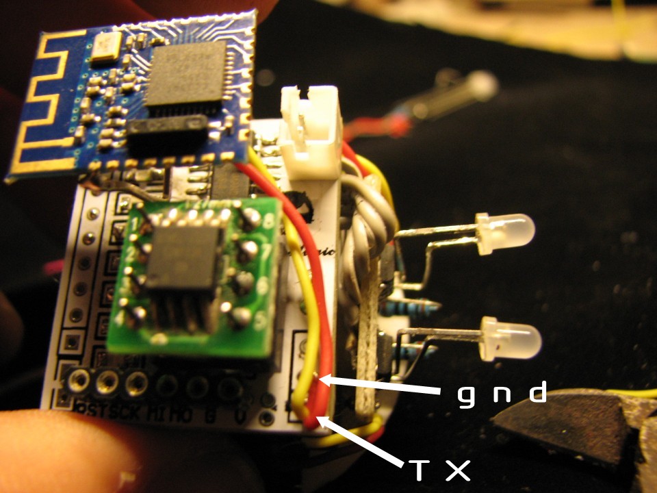
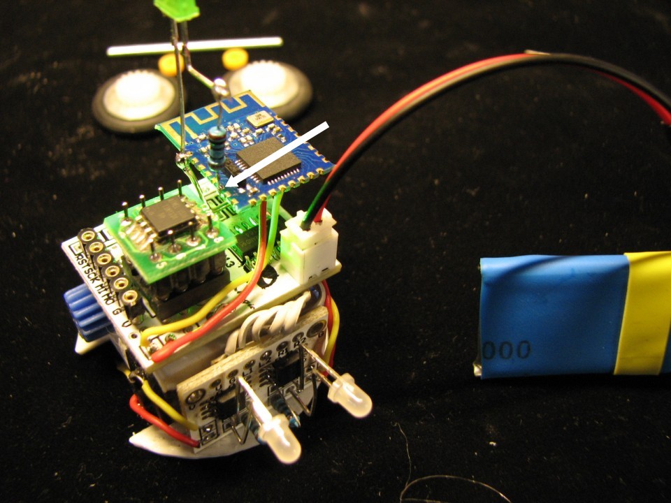
Step 10: Bluetooth Moudle Welding
P03 is the TX
the Metal strip connection to VCC,better to bend to the right shape,then welding to the pad of VCC on the mother board,but need be careful the back ,beacuse we alreading welding the VCC wire of motor driver on it
GND pad is the middle one
TX is bottom
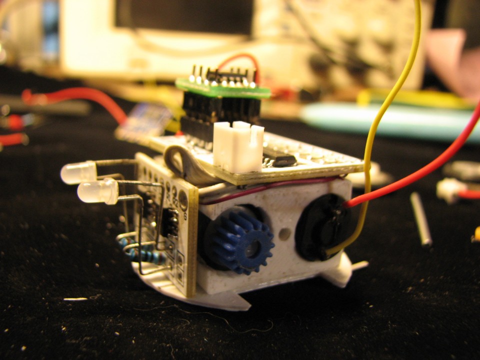
the led connect the 100ohm is Status indicator ,when your phone connect success to the bluetooth moudle,it will light on


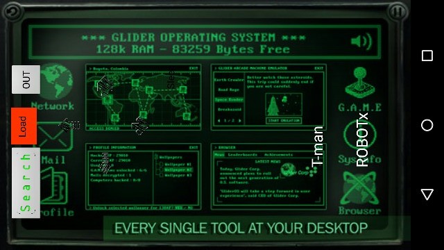
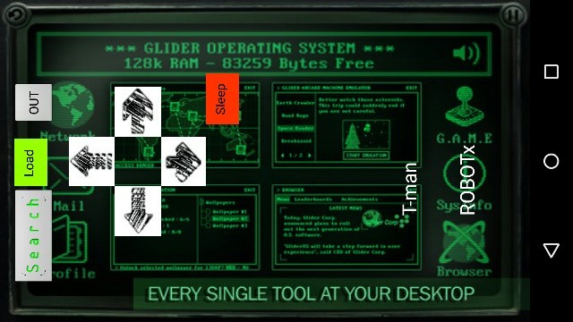
Step 11: Second Test
run the apk on the phone
click the “Search” button,if all the welding is right,the phone can show the robot name on the list of the software interface,one robot,two robot,three………….
click the robot which you want control,then click “Load“ button,the software will open the door of the robot’s world
so you can click the Left,Right,Front,Back
Sleep is for the robot Standby
this is just test
if all ok,next step we install the wheels

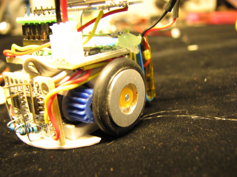
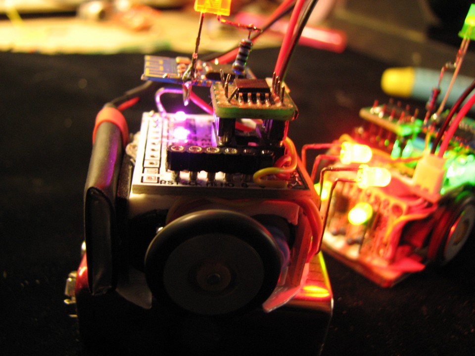
Step 12: Wheels
wheels like picture
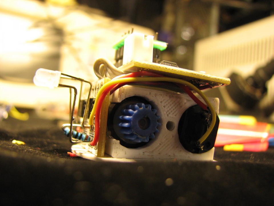
battery glue on the back
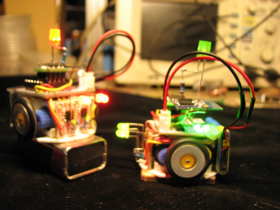
so the robot finished
Let’s celebrate.


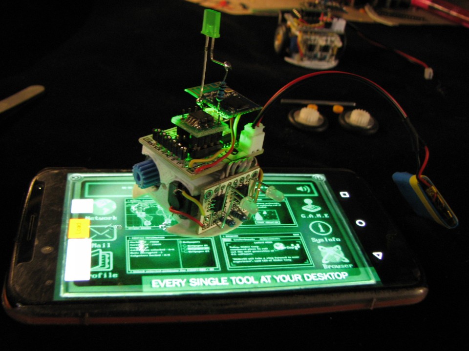
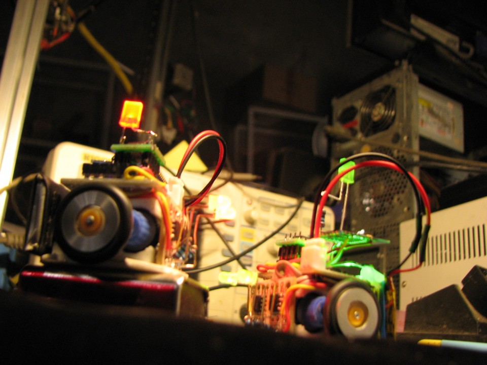
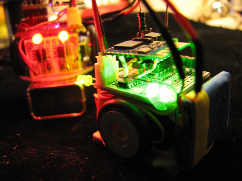
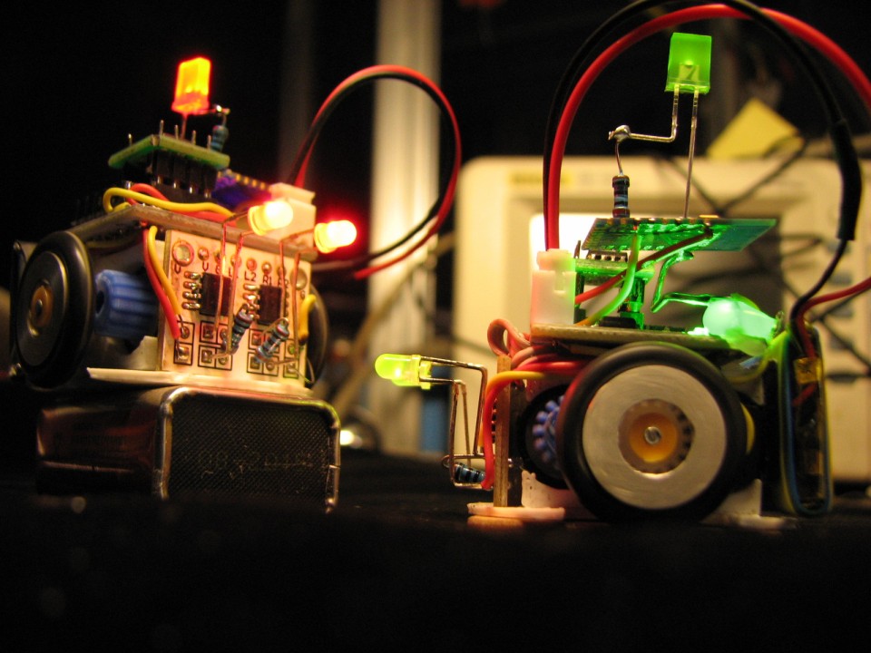
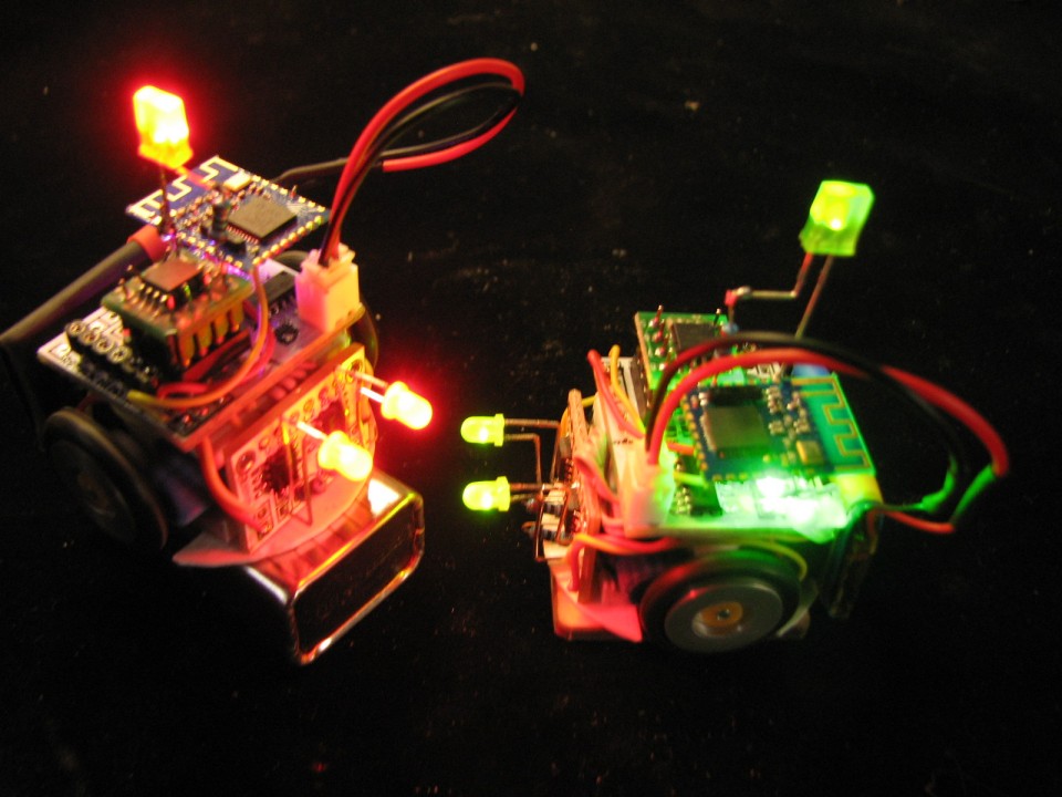
Step 14: FINISHED
the robot finished
Enjoy~

At last,how to use your phone control robot?
Click to get apk and soure code
bluebot1 (下载670)