

Cool Wifi Clock type3
sgtc diy
12月 17, 2021
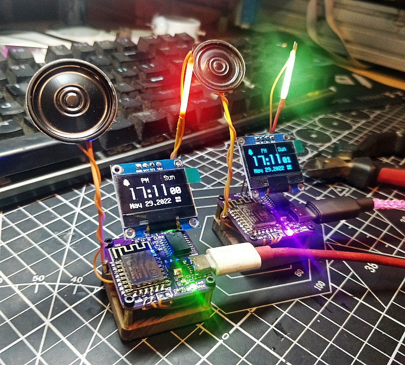
Digital Clock oled display wifi network clock
7月 10, 2022This is a wifi clock .The clock use ds3231 as clock chip, precision is about 2ppm,that means it’s maximum error is about 1 minute per year.It can connect your home wifi through the esp8266 wifi chip .With some simple settings, you can control this clock over the network.It have a funny alarm, you can choose the alarm mode, whether it will keep ringing until you turn it off or only for a minute
Follow our step, you can make a cool network clock yourself
Now let’s start making this alarm clock
DIY VEDIO
Welding Principles
Components are soldered from low to high
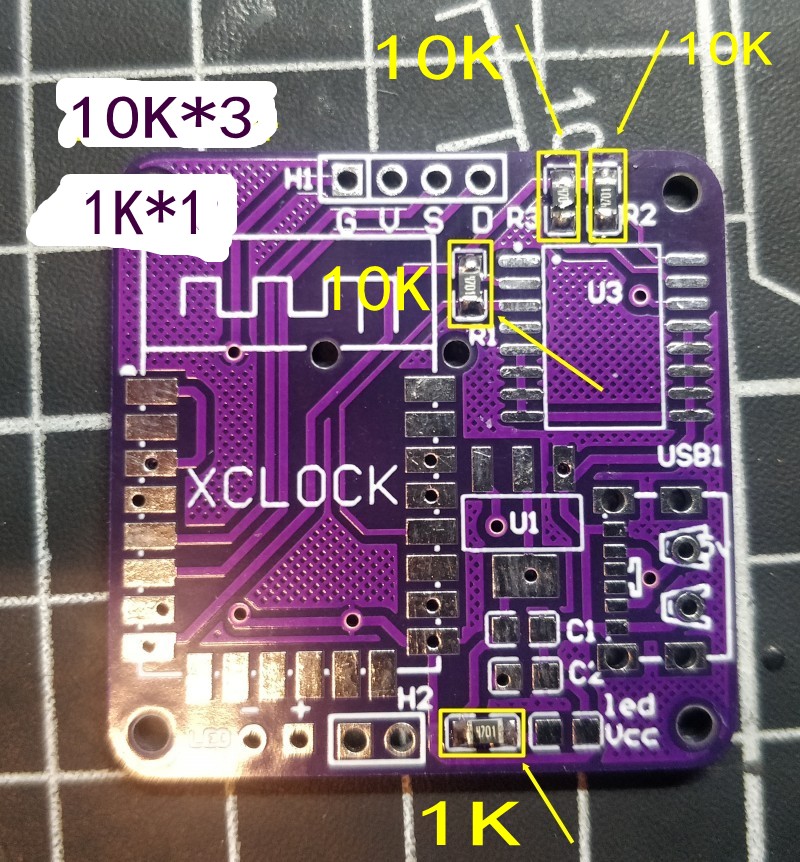
first solder the resistor and capacitor, this is 0805 SMD
Look at the picture, Solder the components to the corresponding positions on the picture
10K*3 and 1K*1
the back of the pcb
10K*1 and 1K*2

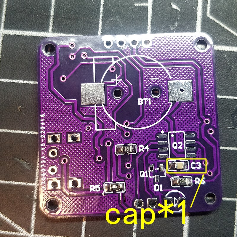
Next Solder the capacitor
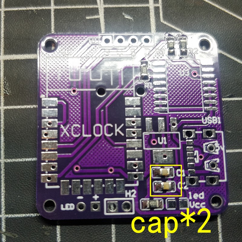
PCB back
Welding power chip,LM1117
this chip can change 5v to 3.3v for the chip working
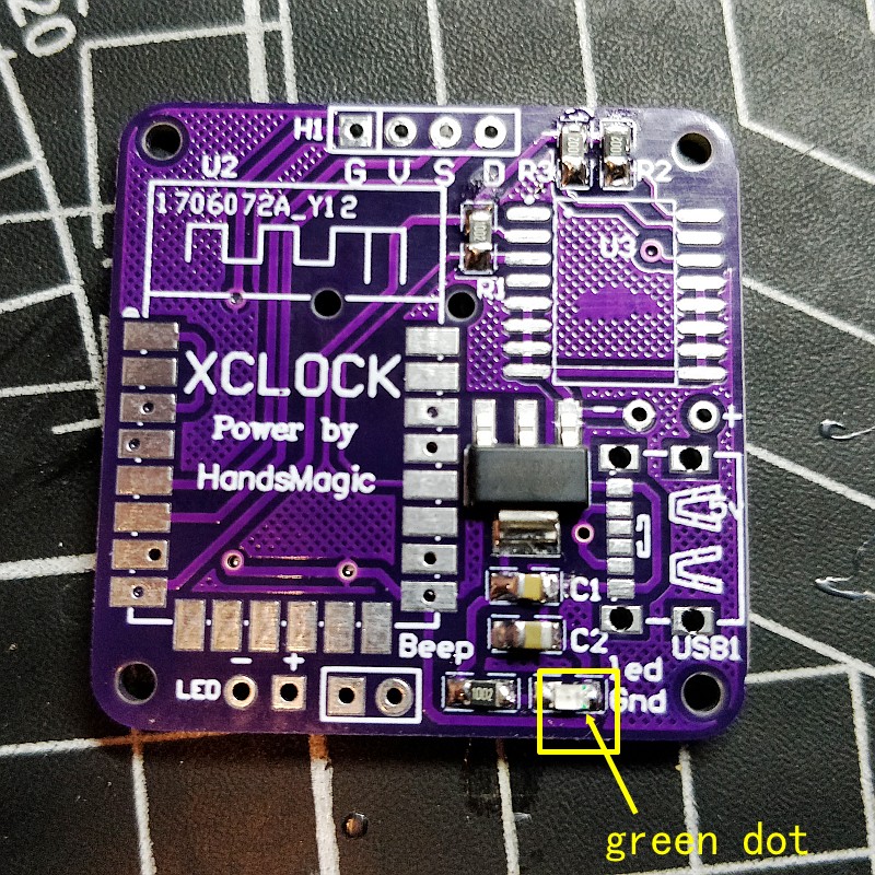
Welding power indicator led
LEDs have positive and negative poles
The green dot is the negative pole, the negative pad is soldered to the right side
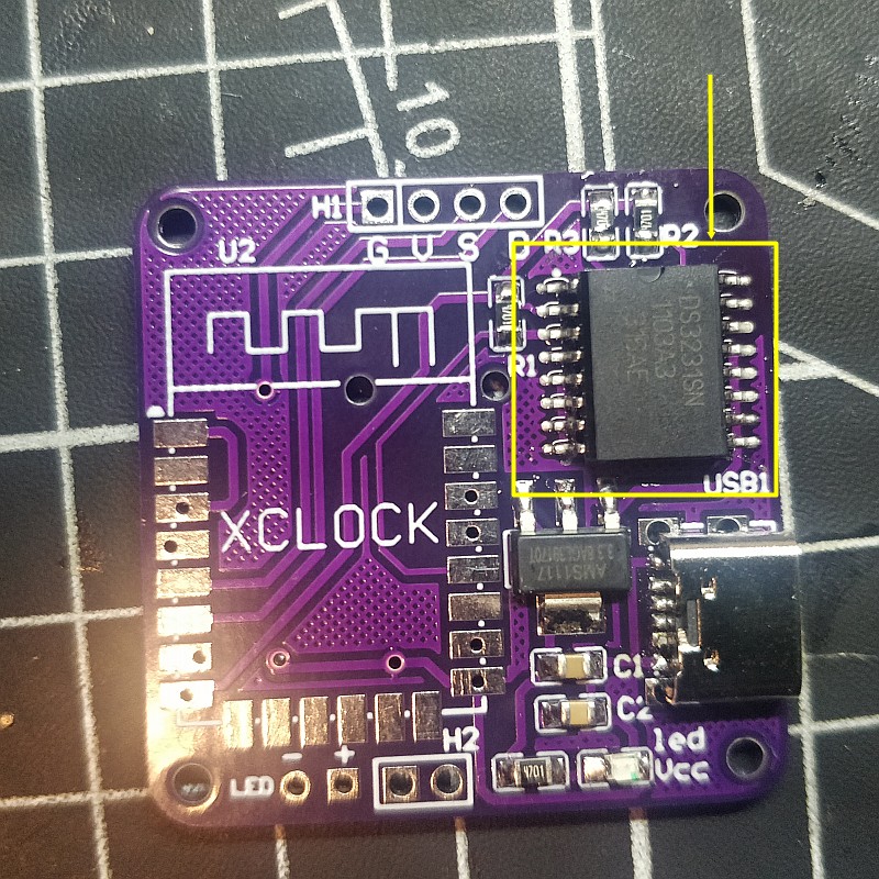
Clock chip,ds3231
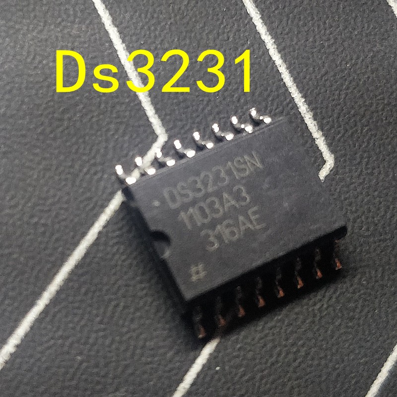
You need to learn to solder the smd , it’s not very difficult
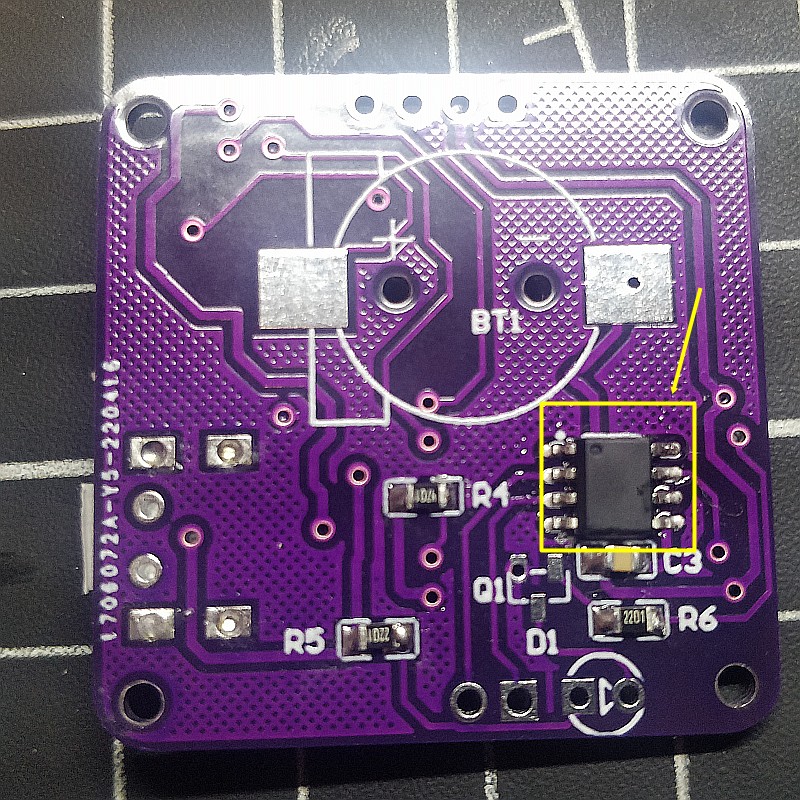
This is the alarm clock chip, which stores audio files
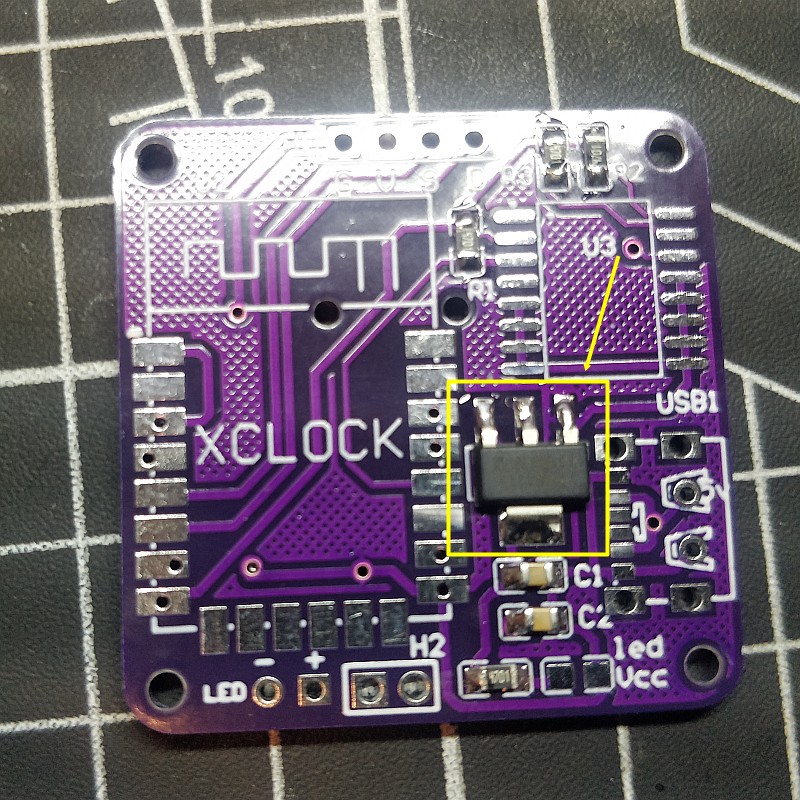
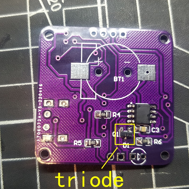
triode
This is used as led driver
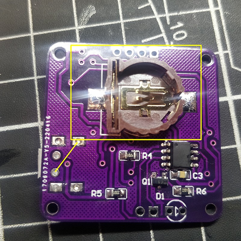
This is the clock chip battery holder
For power failure time memory
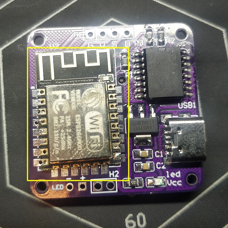
This is the wifi chip which is used for network communication and for controlling the entire clock
At this step, the main pcb has been soldered, finished, now start making the bottom
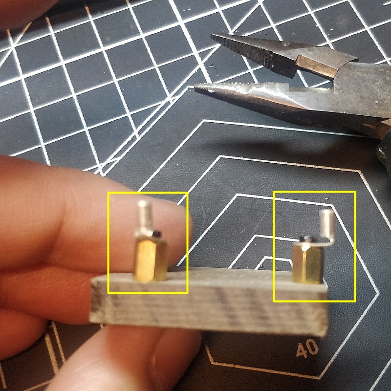
First use screws to install these two bases
These two are used as base for speakers and leds
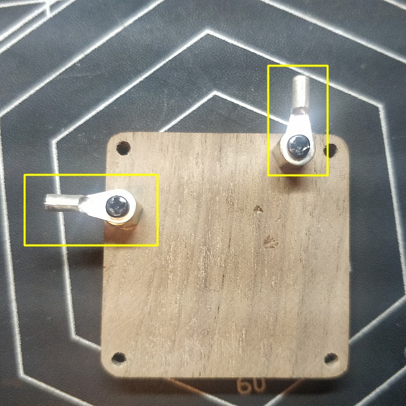
Bend with pliers into right corners
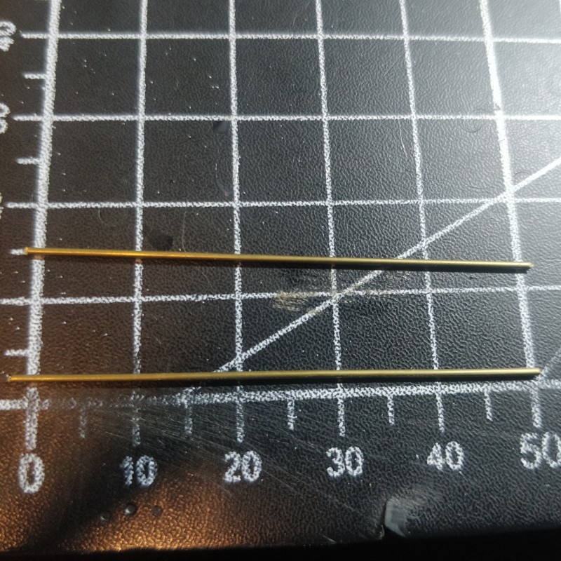
Bronze rod, cut into 5cm
Welded one to the speaker
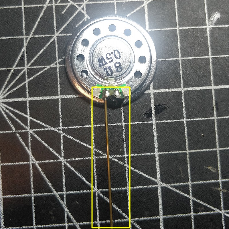

cover a hot tube,This is used as decoration

Another wire

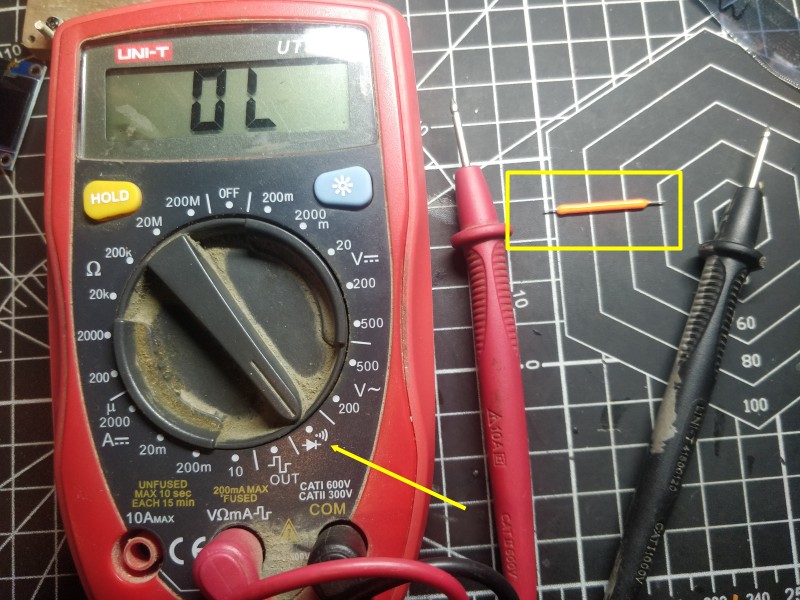
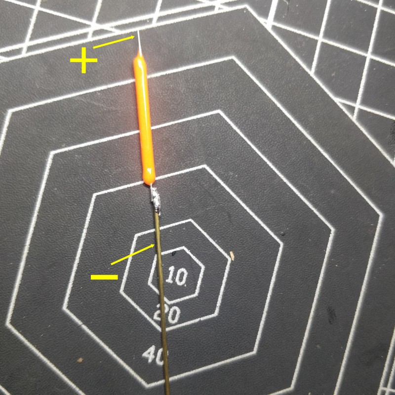
The pins of LED are divided into positive and negative electrodes
You need to use a multimeter to test, which is the positive electrode, which is the negative electrode
If there is no multimeter, welded it freely. If it is not bright in the end, you can exchange the wires of the pin.
Copper rod as negative poles

Welding to the base
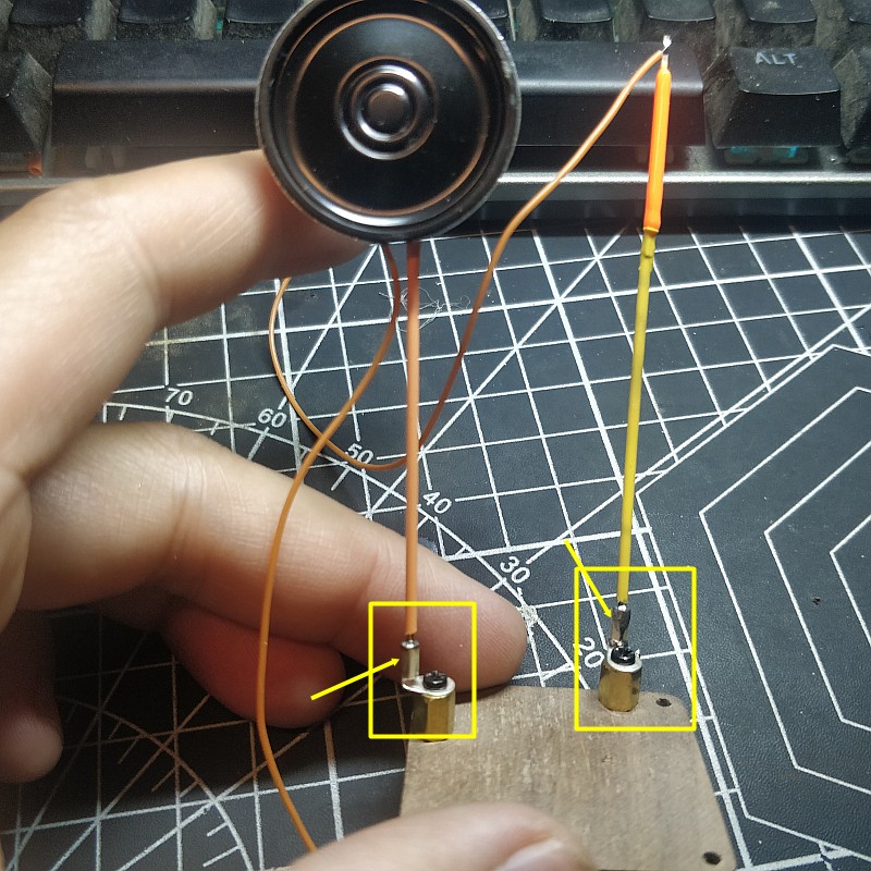
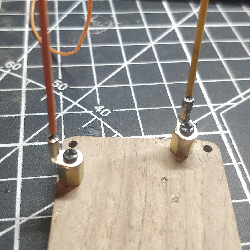
For looks beauty, the wire is wrapped on the copper stick
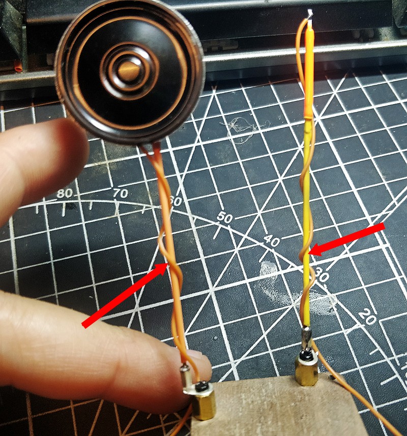
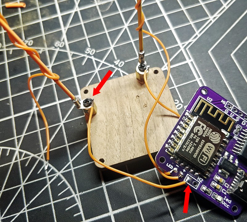
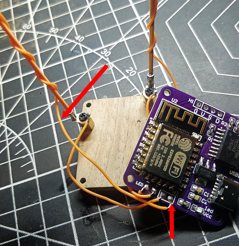
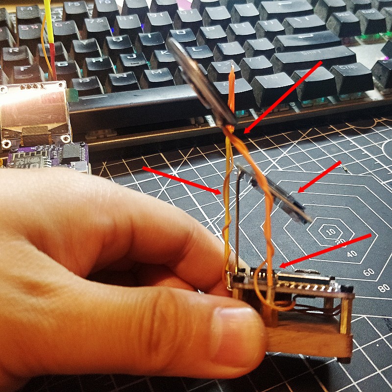
In the position shown in picture, weld two wires
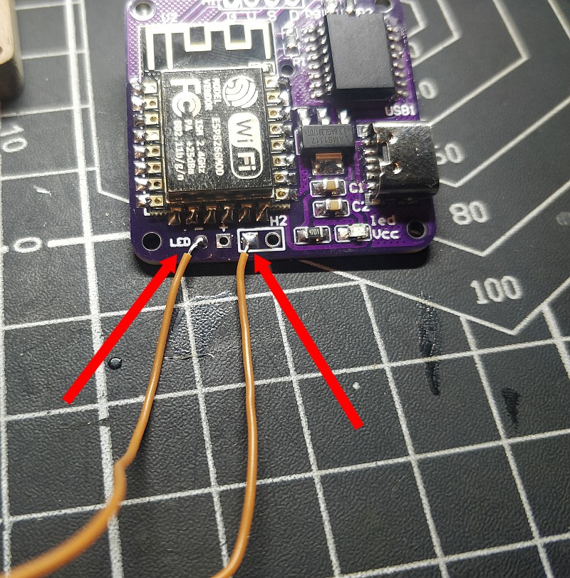
the wire led “-“,to the led base like picture
Led “+”,weld wire

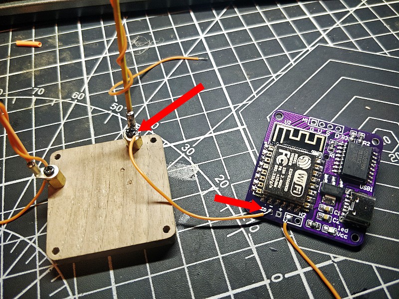
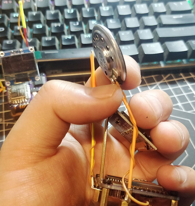
speaker wire
The speaker does not divide positive and negative poles, so the two wires can be exchanged and welded freely
The other wire from the speaker
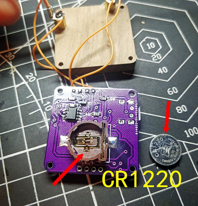
This is the memory battery holder in the back
it is cr1220
We didn’t send batteries, because it can’t ship batteries , you can buy them yourself at the department store
This does not have to be installed, just a function of the power outage preservation time
Four copper columns are mounted on the base
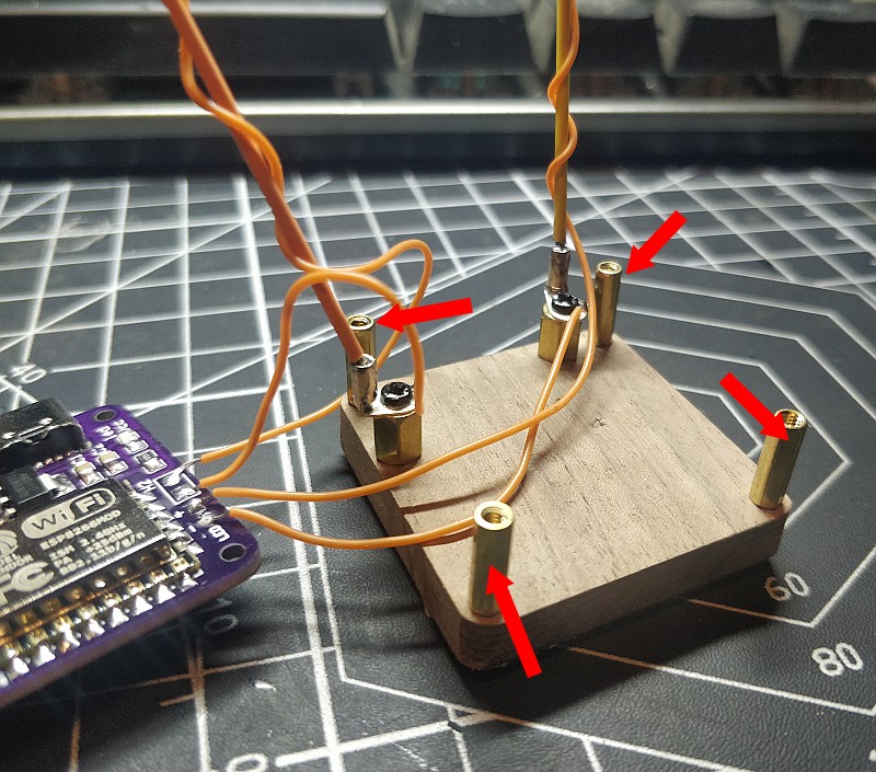
Fix PCB with screws
This is OLED display
You only need four wires to make it work
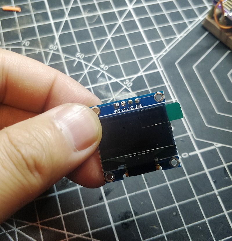
We use four copper rods as the wires
Each is 3.5cm
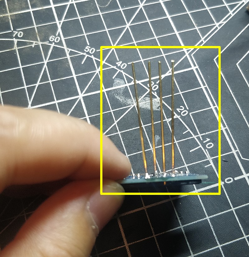
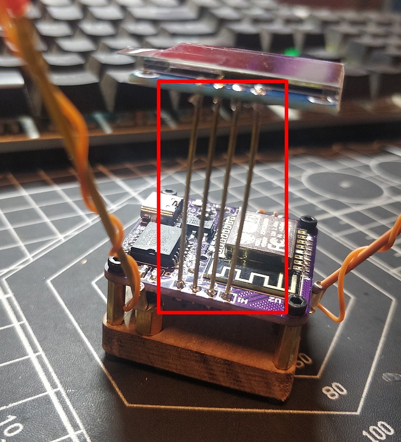
Carefully bend into a 45 degree slope
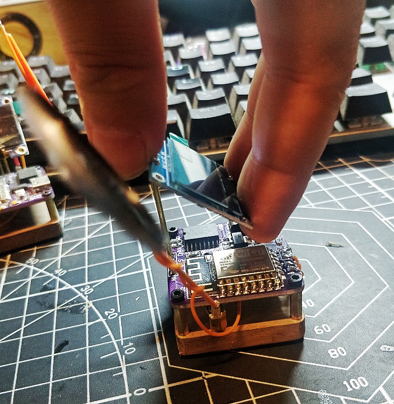
Adjust the Angle of the copper rod ……………..

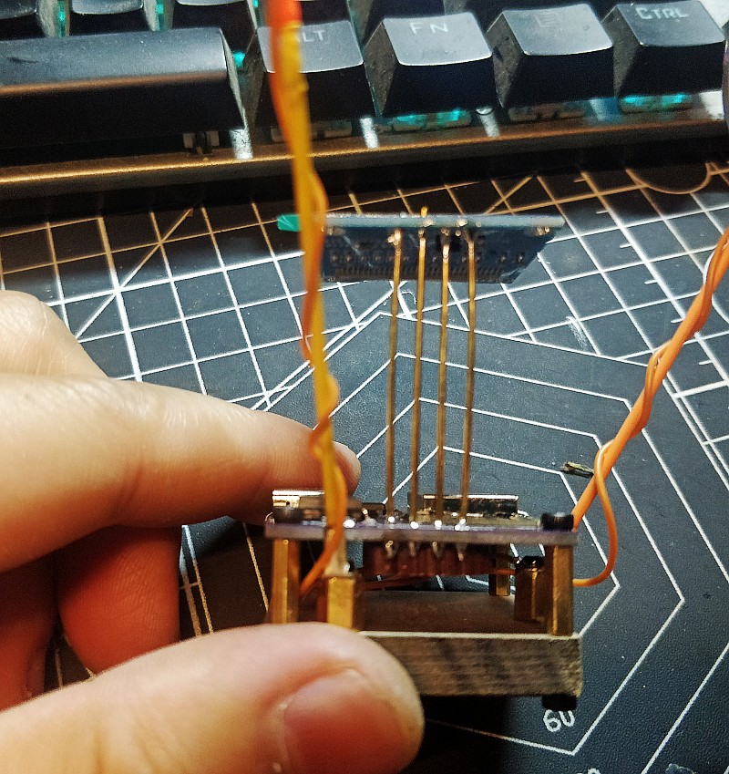
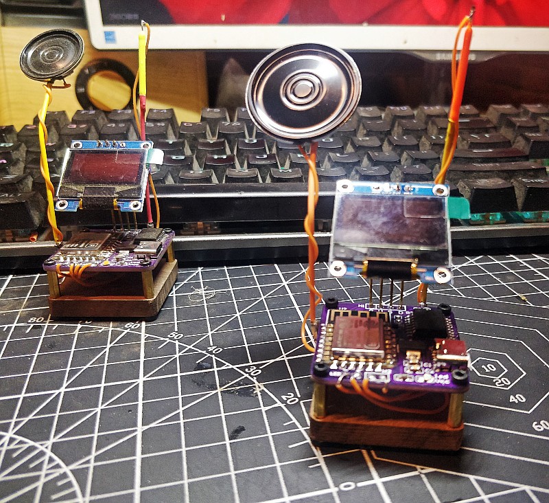
bend it here too
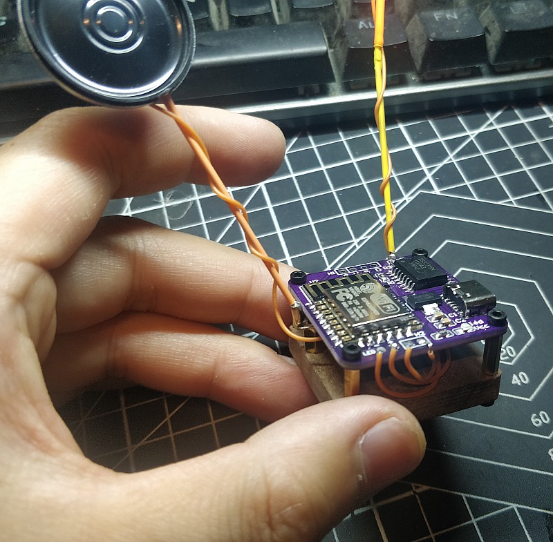
After a slight adjustment of the Angle, we finished the clock
Next step we will tell you how to set up and use this clock
Set Clock
WIFI :AutoconnectAP
Password:password
after you connect to the AutoconnectAP,you choose your home wifi ,the clock will remember it,and it can connect your home wifi